Mitsubishi Lancer Evolution IX. Manual — part 269
IGNITION SWITCH
CHASSIS ELECTRICAL
54A-13
TECHNICAL DESCRIPTION (COMMENT)
• This malfunction may be caused by a defective
immobilizer-ECU, engine-ECU, or a defect in the
communication line between the immobi-
lizer-ECU and engine-ECU. If this malfunction
appears when the MPI system and M.U.T.-II/III
can communicate each other, MPI system diag-
nosis code No.P0513 will reset.
• If the MPI system is normal, the engine control
relay can be determined as normal. In addition, if
the MPI system and M.U.T.-II/III can communi-
cate each other, the circuits between the diagno-
sis connector and the engine-ECU can
determined as normal.
NOTE: If this malfunction appears, MPI system diag-
nosis code No.P0513 will be set.
TROUBLESHOOTING HINTS
• Malfunction of the immobilizer-ECU.
• Malfunction of the engine-ECU.
• The wiring harness or connectors may have
loose, corroded, or damaged terminals, or termi-
nals pushed back in the connector.
DIAGNOSIS PROCEDURE
STEP 1. Check if M.U.T.-II/III can communicate
with the MPI system and if an MPI system
diagnosis code other than P0513 is set.
Q: Can M.U.T.-II/III communicate with the MPI system?
Is an MPI system diagnosis code other than P0513
set?
YES :
Go to Step 2.
NO :
Refer to GROUP 13A, Troubleshooting
.
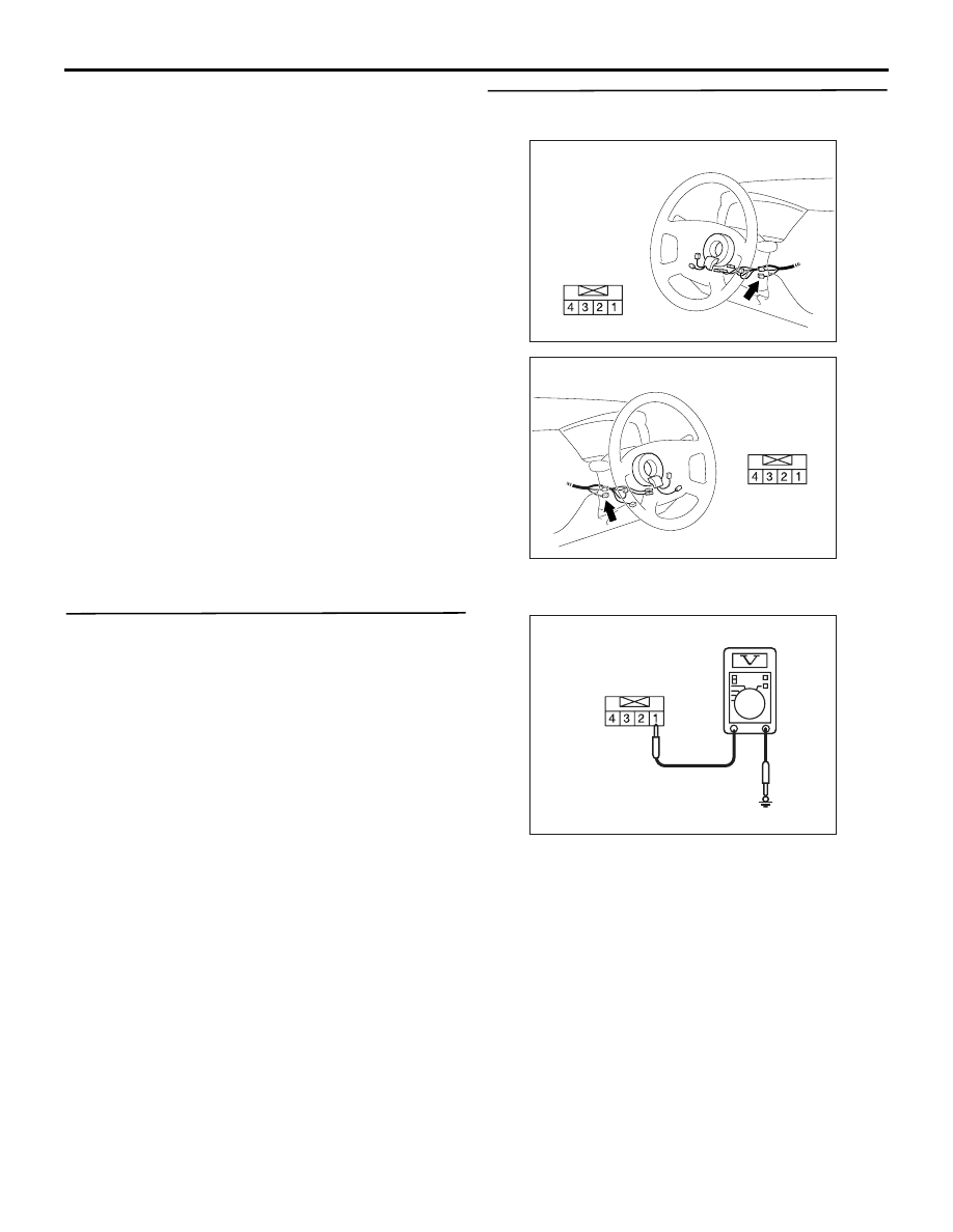
STEP 2. Voltage measurement at
immobilizer-ECU connector C-207-1.
AC310479
Connector: C-207-1 <L.H. drive vehicles>
Harness side
AH
AC310481
Connector: C-207-1 <R.H. drive vehicles>
Harness side
AH
(1) Disconnect immobilizer-ECU connector C-207-1.
(2) Turn the ignition switch to the "ON" position.
AC304844AC
Connector C-207-1
(Harness side)
(3) Measure the voltage between terminal 1 and
earth.
OK: System voltage
Q: Is the check result normal?
YES :
Go to Step 5.
NO :
Go to Step 3.
IGNITION SWITCH
CHASSIS ELECTRICAL
54A-14
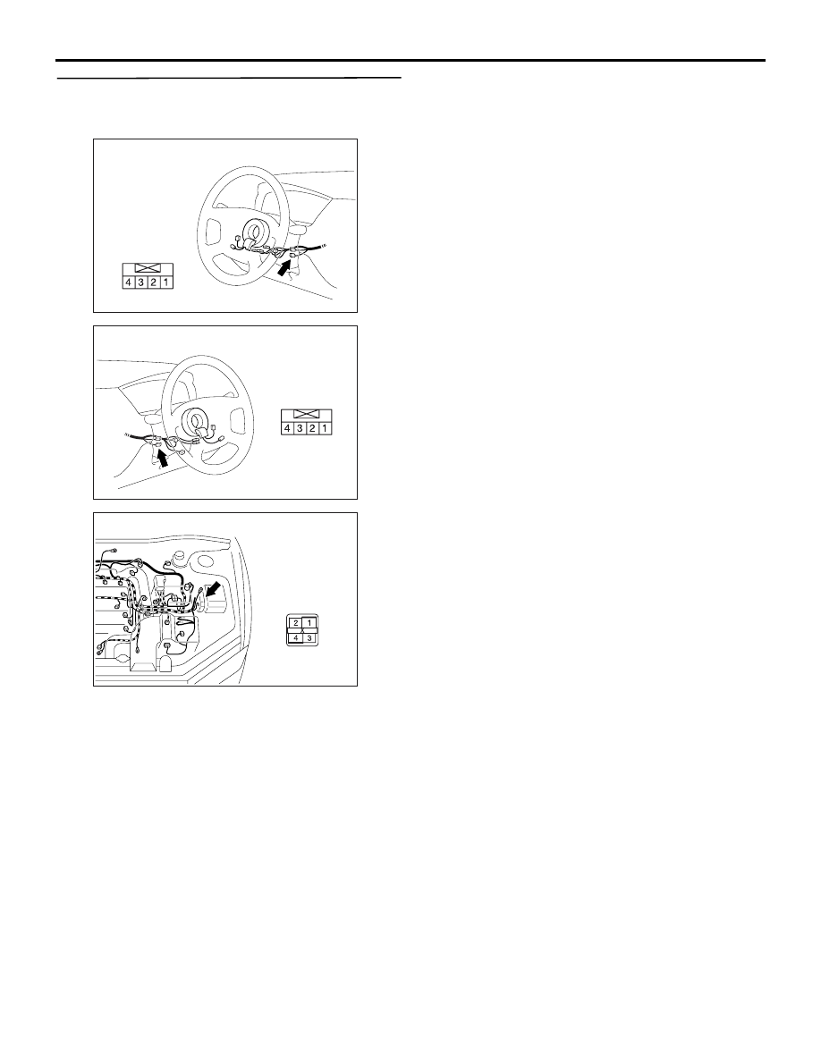
STEP 3. Connector check: Immobilizer-ECU
connector C-207-1 and engine control relay
connector B-12X
AC310479
Connector: C-207-1 <L.H. drive vehicles>
Harness side
AH
AC310481
Connector: C-207-1 <R.H. drive vehicles>
Harness side
AH
AC310439
Connector: B-12X
Harness side
AD
Q: Are immobilizer-ECU connector C-207-1 and
engine control relay connector B-12X in good
condition?
YES :
Go to Step 4.
NO :
Repair or replace the damaged
component(s). Confirm that M.U.T.-II/III
communicates normally.
IGNITION SWITCH
CHASSIS ELECTRICAL
54A-15
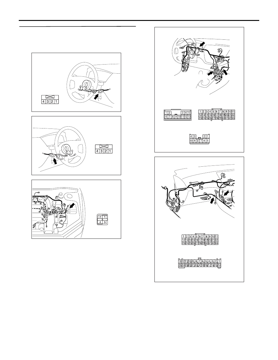
STEP 4. Check the harness wires between
immobilizer-ECU connector C-207-1 (terminal 1)
and engine control relay connector B-12X
(terminal 4).
AC310479
Connector: C-207-1 <L.H. drive vehicles>
Harness side
AH
AC310481
Connector: C-207-1 <R.H. drive vehicles>
Harness side
AH
AC310439
Connector: B-12X
Harness side
AD
AC310447
Connectors: C-21, C-105, C-123
<L.H. drive vehicles>
C-21
C-105
C-105
C-123
AT
C-123(GR)
C-21
AC310455
C-105
C-124
C-105
C-124
AK
Connectors: C-105, C-124
<R.H. drive vehicles>
NOTE: Prior to the wiring harness inspection, check
intermediate connector C-123 <LH drive vehicles>,
C-124 <RH drive vehicles>, joint connector C-21 and
C-105 <LH drive vehicles>, C-105 <RH drive vehi-
cles> and key reminder switch connector C-207, and
repair if necessary.
IGNITION SWITCH
CHASSIS ELECTRICAL
54A-16
Q: Are the harness wires between immobilizer-ECU
connector C-207-1 (terminal 1) and engine control
relay connector B-12X (terminal 4) in good
condition?
YES :
There is no action to be taken.
NO :
Replace damaged component(s). Confirm
that M.U.T.-II/III communicates normally.
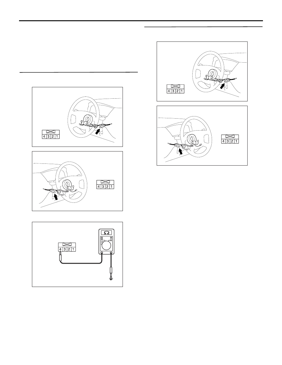
STEP 5. Resistance measurement at
immobilizer-ECU connector C-207-1.
AC310479
Connector: C-207-1 <L.H. drive vehicles>
Harness side
AH
AC310481
Connector: C-207-1 <R.H. drive vehicles>
Harness side
AH
(1) Disconnect immobilizer-ECU connector C-207-1.
AC304851AC
Connector 207-1
(Harness side)
(2) Measure the resistance between terminal 4 and
earth.
OK: 2 ohms or less
Q: Is the check result normal?
YES :
Go to Step 8.
NO :
Go to Step 6.
STEP 6. Connector check: immobilizer-ECU
connector C-207-1
AC310479
Connector: C-207-1 <L.H. drive vehicles>
Harness side
AH
AC310481
Connector: C-207-1 <R.H. drive vehicles>
Harness side
AH
Q: Is immobilizer-ECU connector C-207-1 in good
condition?
YES :
Go to Step 7.
NO :
Repair or replace the damaged
component(s). Confirm that M.U.T.-II/III
communicates normally.
Нет комментариевНе стесняйтесь поделиться с нами вашим ценным мнением.
Текст