Mitsubishi Lancer Evolution IX. Manual — part 574
TRAILING ARM
REAR SUSPENSION
34-11
REMOVAL SERVICE POINT
<<A>> TRAILING ARM ASSEMBLY AND
KNUCKLE DISCONNECTION
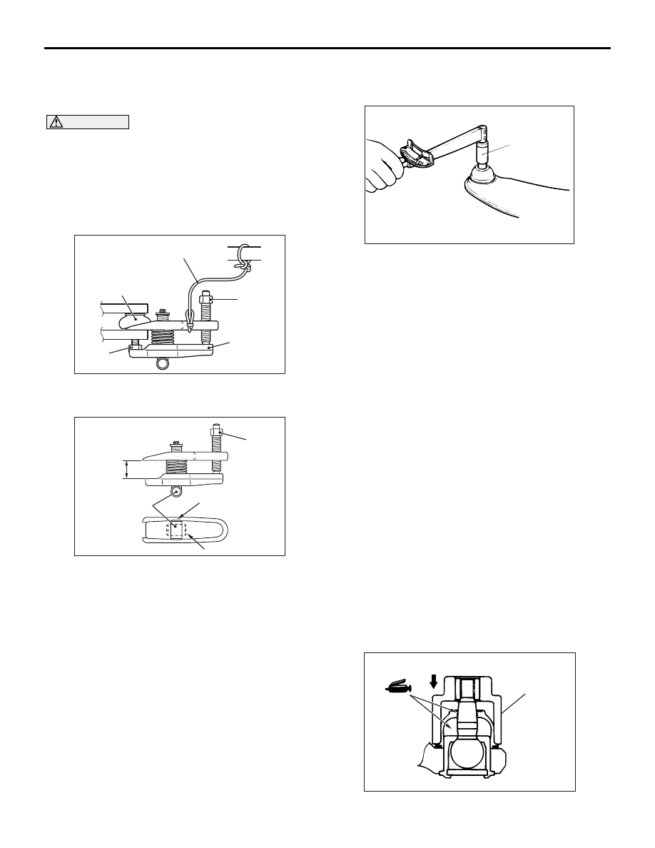
CAUTION
• Do not remove the nut from ball joint. Loosen
it and use special tool ball joint remover
(MB991897 or MB992011) to avoid possible
damage to ball joint threads.
• Hang special tool ball joint remover
(MB991897 or MB992011) with a cord to pre-
vent it from falling.
AC106820 AE
Cord
Bolt
MB991897
or
MB992011
Nut
Ball joint
1. Install the special tool ball joint remover
(MB991897 or MB992011) as shown in the figure.
AC106821
Knob
Parallel
Bolt
Good
Bad
AB
2. Turn the bolt and knob as necessary to make the
jaws of the special tool ball joint remover
(MB991897 or MB992011) parallel, tighten the
bolt by hand and confirm that the jaws are still
parallel.
NOTE: When adjusting the jaws in parallel, make
sure the knob is in the position shown in the fig-
ure.
3. Tighten the bolt with a wrench to disconnect the
trailing arm assembly and the knuckle.
INSPECTION
M1341002300289
BALL JOINT STARTING TORQUE CHECK
ACX00716
MB990326
AB
1. After shaking the ball joint stud several times, use
special tool preload socket (MB990326) to
measure the starting torque of the ball joint.
Standard value: 0.5
− 2.5 N⋅m
2. When the measured value exceeds the standard
value, replace the trailing arm assembly.
3. When the measured value is lower than the
standard value, check that the ball joint turns
smoothly without excessive play. If there is no
excessive play, the ball joint can be reused.
DUST COVER CHECK
1. Check the dust cover for cracks or damage by
pushing it with your finger.
2. If the dust cover is cracked or damaged, replace
the trailing arm assembly.
NOTE: Cracks or damage to the dust cover may
cause damage to the ball joint. When it is dam-
aged during service work, replace the dust cover.
TRAILING ARM BALL JOINT DUST
COVER REPLACEMENT
M1341010900424
Only when the dust cover is damaged accidentally
during service work, replace the dust cover as fol-
lows:
1. Remove the dust cover.
AC212031AB
MB990800
LOWER ARM ASSEMBLY AND ASSIST LINK
REAR SUSPENSION
34-12
2. Fill the multipurpose grease in the dust cover and
lubricate the lip (Amount of filling grease in the
dust cover: approximately 7 g).
3. Using special tool ball joint remover and installer
(MB990800), punch the dust cover until it contacts
the snap ring.
4. Press the dust cover with your finger to check that
there are no cracks or damage in the dust cover.
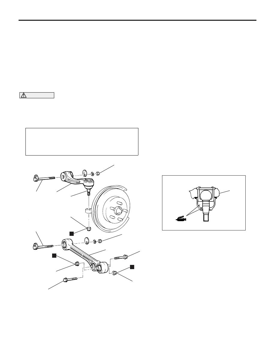
LOWER ARM ASSEMBLY AND ASSIST LINK
REMOVAL AND INSTALLATION
M1341017100065
CAUTION
• During maintenance, take care not to contact the parts or tools to the caliper, because the paint of
caliper will be scratched. And if there is brake fluid on the caliper, wipe out quickly.
•
Post-installation Operation
• Press the dust cover with your finger to check that there
are no cracks or damage in the dust cover.
• Wheel Alignment Check and Adjustment (Refer to
).
AC310785
1
AB
88 ± 10 N·m*
4
N
88 ± 10 N·m*
3
2
N
93 ± 15 N·m*
2
81 ± 6 N·m
N
6
5
93 ± 15 N·m*
6
Lower arm assembly removal
steps
1.
Lower arm assembly to shock
absorber connecting bolt
<<
A
>>
2.
Lower arm assembly mounting bolt
>>
A
<< 3.
Lower arm assembly
Assist link removal steps
<<
B
>>
4.
Assist link and knuckle connection
<<
C
>>
5.
Assist link mounting bolt
6.
Assist link assembly
*
: To prevent bushings from breakage, the parts indicated by * should be temporarily tightened,
and then fully tightened with the vehicle on the ground in the unladen condition.

LOWER ARM ASSEMBLY AND ASSIST LINK
REAR SUSPENSION
34-13
REMOVAL SERVICE POINTS
<<A>> LOWER ARM ASSEMBLY MOUNT-
ING BOLT REMOVAL
AC310794
Mating marks
AB
Make mating marks on the lower arm and the
decentering cam bolt, then remove the lower arm
and the decentering cam bolt.
<<B>> ASSIST LINK AND KNUCKLE
DISCONNECTION
CAUTION
• Do not remove the nut from ball joint. Loosen
it and use special tool ball joint remover
(MB991897 or MB992011) to avoid possible
damage to ball joint threads.
• Hang special tool ball joint remover
(MB991897 or MB992011) with a cord to pre-
vent it from falling.
AC106820 AE
Cord
Bolt
MB991897
or
MB992011
Nut
Ball joint
1. Install special tool ball joint remover (MB991897
or MB992011) as shown in the figure.
AC106821
Knob
Parallel
Bolt
Good
Bad
AB
2. Turn the bolt and knob as necessary to make the
jaws of special tool ball joint remover (MB991897
or MB992011) parallel, tighten the bolt by hand
and confirm that the jaws are still parallel.
NOTE: When adjusting the jaws in parallel, make
sure the knob is in the position shown in the fig-
ure.
3. Tighten the bolt with a wrench to disconnect the
assist link assembly and the knuckle.
<<C>> ASSIST LINK MOUNTING BOLT
REMOVAL
AC310795
Mating marks
Eccentric
cam bolt
AB
Make mating marks on the assist link and the
decentering cam bolt, then remove the toe control
arm and the decentering cam bolt.
INSTALLATION SERVICE POINT
>>A<< LOWER ARM ASSEMBLY INSTAL-
LATION
AC310797AB
With countersunk Ø10mm:
LH side lower arm assembly
With red marking: RH side
lower arm assembly
Check the identification mark, install the lower arm
assembly.

LOWER ARM ASSEMBLY AND ASSIST LINK
REAR SUSPENSION
34-14
INSPECTION
M1341017200051
ASSIST LINK BALL JOINT STARTING
TORQUE CHECK
ACX00716
MB990326
AB
1. After shaking the assist link ball joint stud several
times, measure the starting torque of the assist
link ball joint by using special tool preload socket
(MB990326).
Standard value: 0.5
− 2.5 N⋅m
2. When the measured value exceeds the standard
value, replace the assist link.
3. When the measured value is lower than the
standard value, check that the assist link ball joint
turns smoothly without excessive play. If there is
no excessive play, the ball joint can be reused.
ASSIST LINK SLIDE BUSHING STARTING
TORQUE CHECK
AC212117
MB990326
AB
1. After inserting the bolt to the assist link slide bush
and attaching the washer in the opposite
direction, install the nut. After rotating the inner
sleeve (include the washer) several times,
measure the starting torque of the assist link slide
bushing by using special tool preload socket
(MB990326).
Standard value: 0.5
− 2.0 N⋅m
2. When the measured value exceeds the standard
value, replace the assist link.
3. When the measured value is lower than the
standard value, check that the assist link slide
bushing turns smoothly without excessive play. If
there is no excessive play, the slide bushing can
be reused.
ASSIST LINK BALL JOINT DUST COVER
CHECK
1. Check the dust cover for cracks or damage by
pushing it with your finger.
2. If the dust cover is cracked or damaged, replace
the trailing arm assembly.
NOTE: Cracks or damage of the dust cover may
cause damage to the ball joint. When it is dam-
aged during service work, replace the dust cover.
LOWER ARM PILLOW BALL BUSHING
STARTING TORQUE CHECK
AC310798
MB990326
AB
Pillow ball bushing
1. Insert the bolt to the lower arm pillow ball bushing,
in the opposite direction, insert the washer then
install the nut. After rotating the inner sleeve
(contained washer) several times, measure the
starting torque of the lower arm below ball
bushing using special tool preload socket
(MB990326).
Standard value: 0.5
− 3.0 N⋅m
2. When the measured value exceeds the standard
value, replace the lower arm assembly.
Нет комментариевНе стесняйтесь поделиться с нами вашим ценным мнением.
Текст