Mitsubishi Lancer Evolution IX. Manual — part 123

SYMPTOM PROCEDURES
SMART WIRING SYSTEM (SWS) NOT USING SWS MONITOR
54B-55
COMMENT ON TROUBLE SYMPTOM
If a door can not be locked or unlocked by the central
door locking system, the door lock actuator may be
defective.
POSSIBLE CAUSES
• Malfunction of the door lock actuator
• Damaged harness wires and connectors
DIAGNOSIS PROCEDURE
Step 1. Confirm which door lock actuator is
defective.
Q: Which door fails to lock correctly?
Driver's door :
Go to Step 2.
Front passenger's door :
Go to Step 6.
Rear right door :
Go to Step 10.
Rear left door :
Go to Step 14.
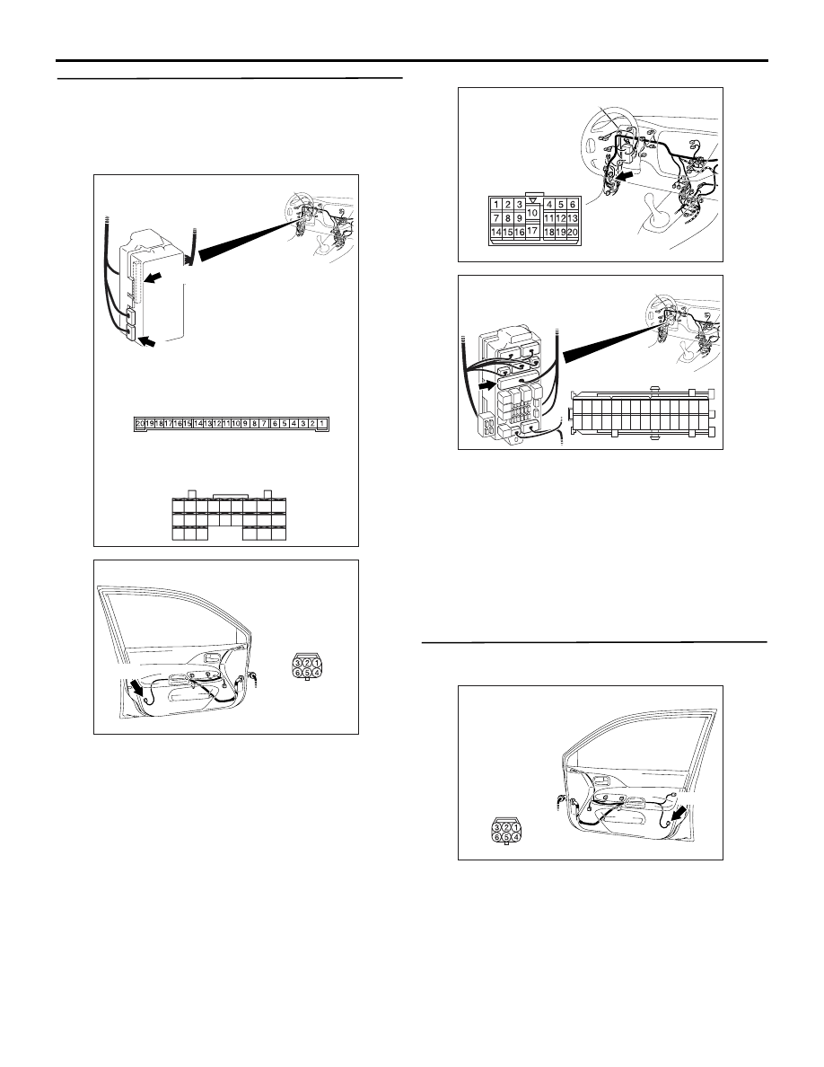
Step 2. Connector check: E-04 front door lock
actuator (LH) connector
Q: Is the check result normal?
YES :
Go to Step 3.
NO :
Repair the defective connector.
Step 3. Check the front door lock actuator (LH)
Check that the front door lock actuator (LH) works
normally. Refer to GROUP 42
− Door
Q: Is the check result normal?
YES :
Go to Step 4.
NO :
Replace the front door lock actuator (LH).
Step 4. Connector check: C-226, C-227
ETACS-ECU connector
Q: Is the check result normal?
YES :
Go to Step 5.
NO :
Repair the defective connector.
AC310484
Harness side
AB
Connector: E-04 <LHD>
E-04(B)
Front door (LH)
AC310451
Connectors: C-226, C-227 <LHD>
AB
Junction block (rear view)
Junction block side
C-227
C-226
C-227
Harness side
C-226
28
37
43
29
44
38
23
32
41
24
25
26
27
34
42
36 35
33
21
22
30
39
40
31
SYMPTOM PROCEDURES
SMART WIRING SYSTEM (SWS) NOT USING SWS MONITOR
54B-56
Step 5. Check the wiring harness from C-226
ETACS-ECU connector terminal No.12 and C-227
ETACS-ECU connector terminal No.22 to E-04
front door lock actuator (LH) connector terminal
Nos.4 and 6.
NOTE:
Prior to the wiring harness inspection, check interme-
diate connector C-17 and junction block connector
C-214, and repair if necessary.
• Check the input and output lines for open circuit.
Q: Is the check result normal?
YES :
The trouble can be an intermittent
malfunction (Refer to GROUP 00
− How to
Cope with Intermittent Malfunction
NO :
Repair the wiring harness.
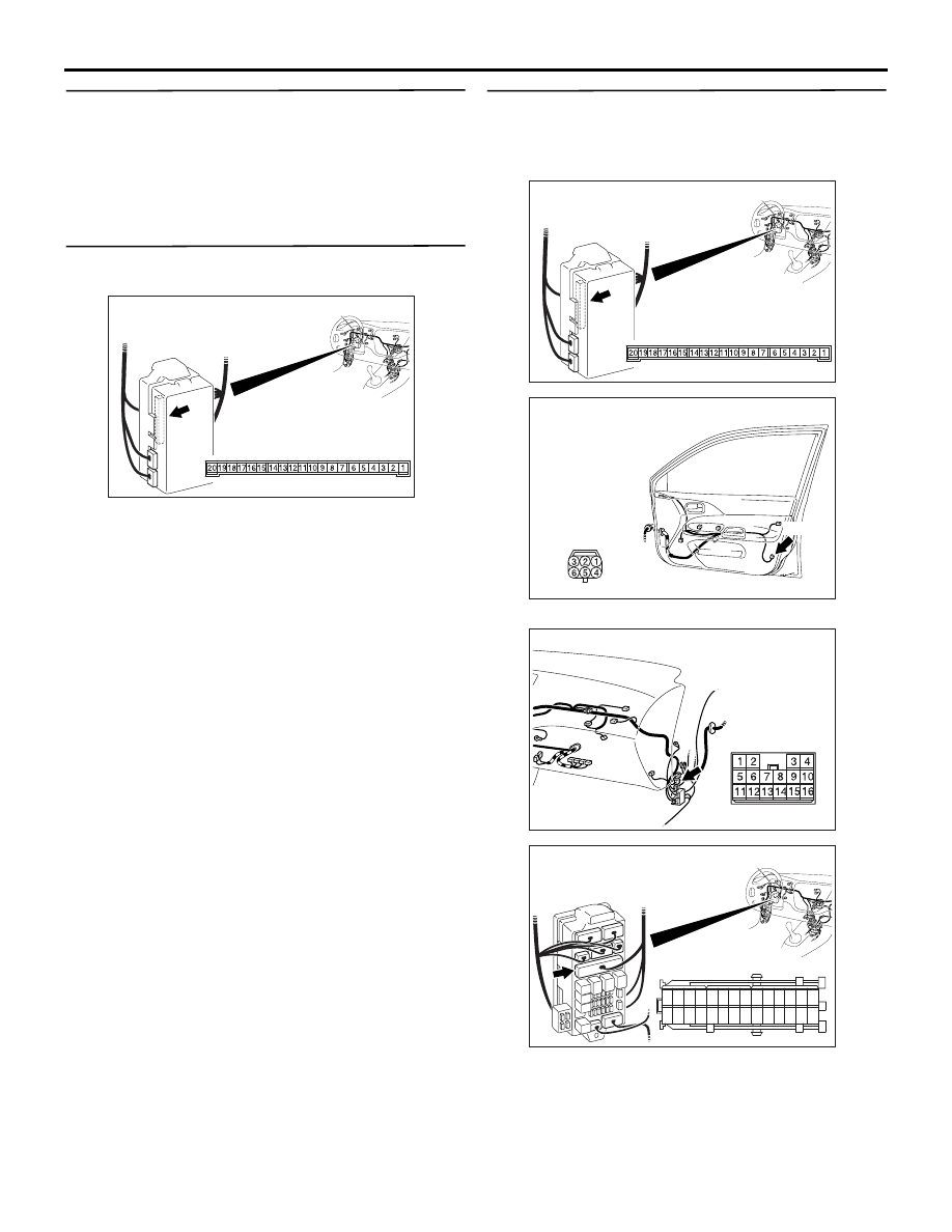
Step 6. Connector check: E-15 front door lock
actuator (RH) connector
Q: Is the check result normal?
YES :
Go to Step 7.
NO :
Repair the defective connector.
AC310451
Connectors: C-226, C-227 <LHD>
AB
Junction block (rear view)
Junction block side
C-227
C-226
C-227
Harness side
C-226
28
37
43
29
44
38
23
32
41
24
25
26
27
34
42
36 35
33
21
22
30
39
40
31
AC310484
Harness side
AB
Connector: E-04 <LHD>
E-04(B)
Front door (LH)
AC310446
Connector: C-17 <LHD>
AE
AC310448
Harness side
Junction block (front view)
Connector: C-214 <LHD>
AE
21
7
16 15
17
18
20 19
1
2
3
4
5
6
23 22
24
25
28
26
27
9
8
10
11
14
12
13
AC310488
Harness side
AB
Connector: E-15 <LHD>
E-15(B)
Front door (RH)
SYMPTOM PROCEDURES
SMART WIRING SYSTEM (SWS) NOT USING SWS MONITOR
54B-57
Step 7. Check the front door lock actuator (RH).
Check that the front door lock actuator (RH) works
normally. Refer to GROUP 42
− Door
Q: Is the check result normal?
YES :
Go to Step 8.
NO :
Replace the front door lock actuator (RH).
Step 8. Connector check: C-226 ETACS-ECU
connector
Q: Is the check result normal?
YES :
Go to Step 9.
NO :
Repair the defective connector.
Step 9. Check the wiring harness from C-226
ETACS-ECU connector terminal Nos.12 and 13 to
E-15 front door lock actuator (RH) connector
terminal Nos.4 and 6.
NOTE:
Prior to the wiring harness inspection, check interme-
diate connector C-110 and junction block connector
C-214, and repair if necessary.
• Check the input and output lines for open circuit.
AC310450
Connector: C-226 <LHD>
AB
Junction block side
Junction block (rear view)
AC310450
Connector: C-226 <LHD>
AB
Junction block side
Junction block (rear view)
AC310488
Harness side
AB
Connector: E-15 <LHD>
E-15(B)
Front door (RH)
AC310452
Connector: C-110 <LHD>
AC
AC310448
Harness side
Junction block (front view)
Connector: C-214 <LHD>
AE
21
7
16 15
17
18
20 19
1
2
3
4
5
6
23 22
24
25
28
26
27
9
8
10
11
14
12
13

SYMPTOM PROCEDURES
SMART WIRING SYSTEM (SWS) NOT USING SWS MONITOR
54B-58
Q: Is the check result normal?
YES :
The trouble can be an intermittent
malfunction (Refer to GROUP 00
− How to
Cope with Intermittent Malfunction
NO :
Repair the wiring harness.
Step 10. Connector check: E-18 rear door lock
actuator (RH) connector
Q: Is the check result normal?
YES :
Go to Step 11.
NO :
Repair the defective connector.
Step 11. Check the rear door lock actuator (RH).
Check that the rear door lock actuator (RH) is in
good condition. Refer to GROUP 42
− Door
Q: Is the check result normal?
YES :
Go to Step 12.
NO :
Replace the rear door lock actuator (RH).
Step 12. Connector check: C-226 ETACS-ECU
connector
Q: Is the check result normal?
YES :
Go to Step 13.
NO :
Repair the defective connector.
Step 13. Check the wiring harness from C-226
ETACS-ECU connector terminal Nos.12 and 13 to
E-18 rear door lock actuator (RH) connector
terminal Nos.4 and 6.
AC310491
Harness side
AB
Connector: E-18
E-18 (B)
Rear door (RH)
AC310450
Connector: C-226 <LHD>
AB
Junction block side
Junction block (rear view)
AC310450
Connector: C-226 <LHD>
AB
Junction block side
Junction block (rear view)
AC310491
Harness side
AB
Connector: E-18
E-18 (B)
Rear door (RH)
Нет комментариевНе стесняйтесь поделиться с нами вашим ценным мнением.
Текст