Mitsubishi Lancer Evolution IX. Manual — part 445
TROUBLESHOOTING
MULTIPORT FUEL INJECTION (MPI)
13A-255
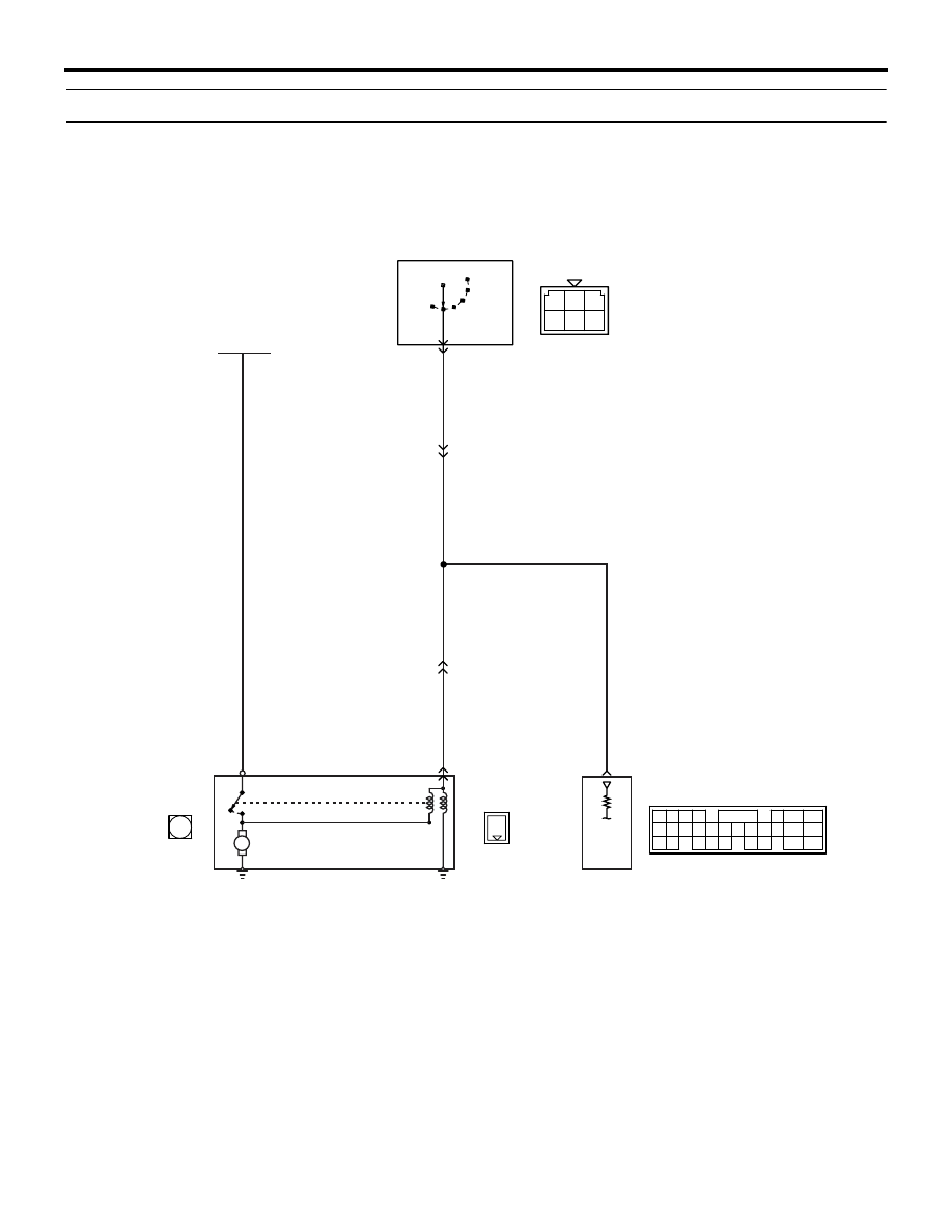
Inspection Procedure 5: Starting Impossible (No Initial Combustion)
OPERATION
• If the ignition switch is turned to "START" posi-
tion, battery voltage is applied to starter (terminal
No. 1).
• If the ignition switch is turned to "START" posi-
tion, battery voltage is applied to engine-ECU
(terminal No. 68) from ignition switch. Because of
this, engine-ECU detects that the engine is
cranked.
COMMENT ON TROUBLE SYMPTOM
• Failure is possibly caused by failed starter itself
or failed related circuit.
PROBABLE CAUSES
• Failed battery
• Failed starter motor
• Open/short circuit in starter associated circuit or
loose connector contact
AK501826
1
1
1 2 3
4 5 6
M
65
43
50
42
49
41
48
60 61
64
46 47
58 59
67 68
45
56
66
52
51
44
53
62
54
63
57
55
Battery
OFF
ON
AB
Starter
B-19
B-21
(MU801211)
C-119
(MU803782)
C-208
B-R
B-R
B-R
B-R
B-Y
B-L
68
R
IG2
ST
LOCK
ACC
IG1
Ignition switch
Starter circuit
Wire colour code
B: Black LG: Light green G: Green L: Blue W: White Y: Yellow SB: Sky blue BR: Brown O: Orange GR: Gray
R: Red P: Pink V: Violet PU: Purple
Engine-ECU
5
7
C-123
3
B-14
1
B-21
1
B-19
TROUBLESHOOTING
MULTIPORT FUEL INJECTION (MPI)
13A-256
DIAGNOSIS PROCEDURE
STEP 1. Check battery voltage.
• Measure battery voltage at cranking.
OK: 8 V or higher
Q: Is the check result normal?
YES :
Go to Step 2 .
NO :
Check battery (Refer to GROUP 54A
−
Battery
− On-vehicle Service − Battery Test
).
STEP 2. M.U.T.-II/III data list
• Item No. 18: Cranking signal
OK:
ON (Ignition switch: ST)
OFF (Ignition switch: ON)
Q: Is the check result normal?
YES :
Go to Step 8 .
NO :
Go to Step 3 .
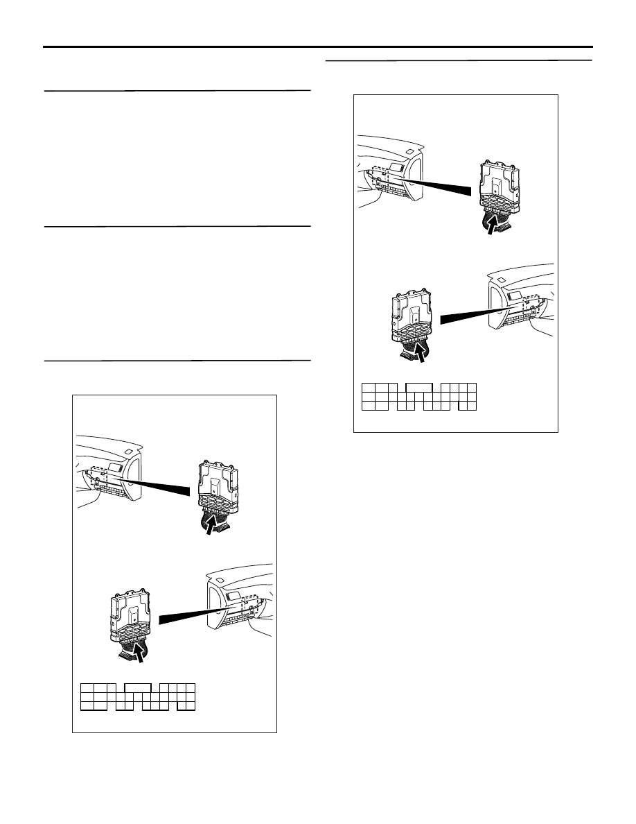
STEP 3. Connector check: C-119 engine-ECU
connector
Q: Is the check result normal?
YES :
Go to Step 4 .
NO :
Repair or replace the connector.
STEP 4. Perform voltage measurement at C-119
engine-ECU connector.
• Disconnect connector, and measure at the har-
ness side.
• Ignition switch: ST
• Voltage between terminal No. 68 and earth.
OK: System voltage
Q: Is the check result normal?
YES :
Go to Step 7 .
NO :
Go to Step 5 .
AK501994
65
43
50
42
49
41
48
60
61
64
46
47
58
59
67
68
45
56
66
52 51
44
53
62
54
63
57
55
AB
Connector: C-119
C-119 (GR)
C-119 (GR)
Harness side connector
<L. H. drive vehicles>
<R. H. drive vehicles>
AK501994
65
43
50
42
49
41
48
60
61
64
46
47
58
59
67
68
45
56
66
52 51
44
53
62
54
63
57
55
AB
Connector: C-119
C-119 (GR)
C-119 (GR)
Harness side connector
<L. H. drive vehicles>
<R. H. drive vehicles>
TROUBLESHOOTING
MULTIPORT FUEL INJECTION (MPI)
13A-257
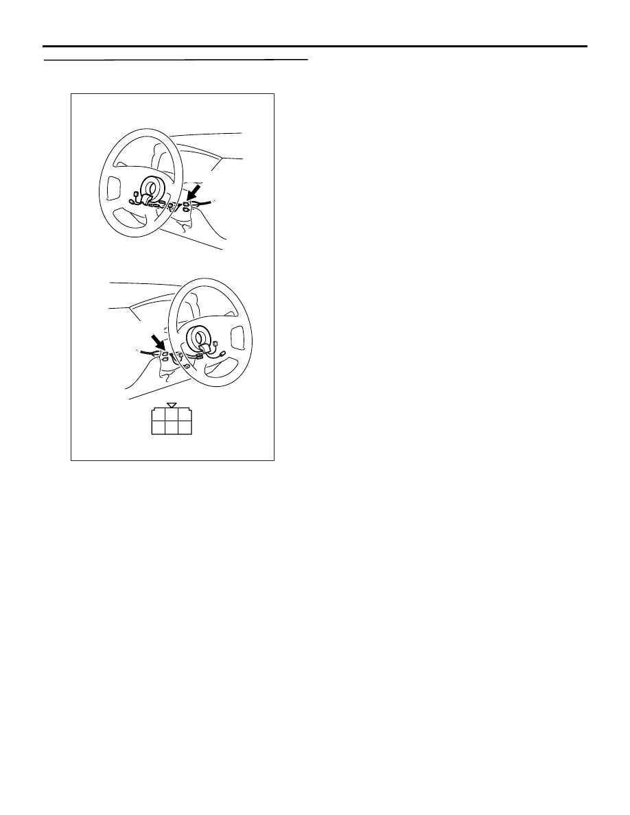
STEP 5. Connector check: C-208 ignition switch
connector
Q: Is the check result normal?
YES :
Go to Step 6 .
NO :
Repair or replace the connector.
AK305251
1
2
3
4
5
6
Harness side connector
Connector: C-208
C-208
<L. H. drive vehicles>
<R. H. drive vehicles>
C-208
AB
TROUBLESHOOTING
MULTIPORT FUEL INJECTION (MPI)
13A-258
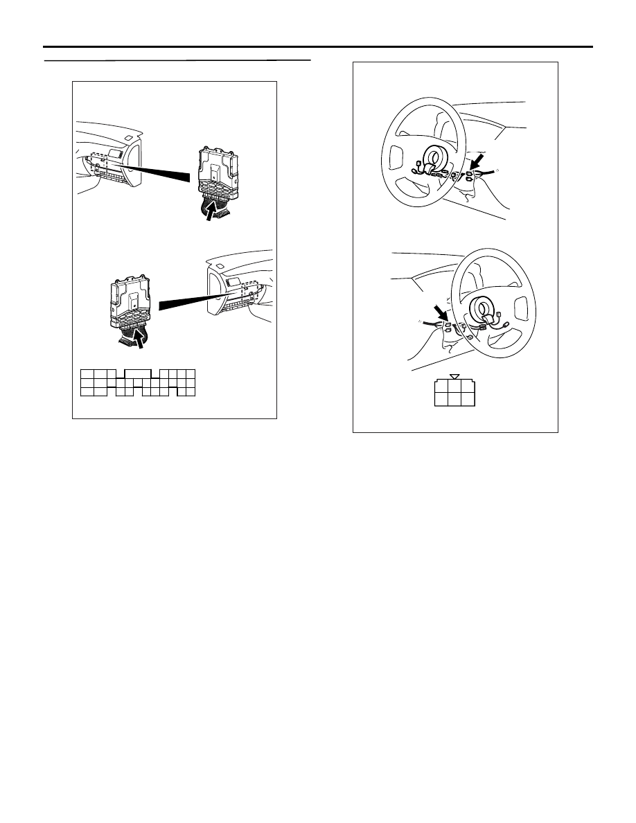
STEP 6. Check ignition switch.
• Check ignition switch (Refer to GROUP 54A −
Ignition Switch
− Ignition Switch − Inspection
).
Q: Is the check result normal?
YES :
Check intermediate connectors C-123, and
repair if necessary. If intermediate
connectors are normal, check and repair
harness between C-119 (terminal No. 68)
inhibitor switch connector and C-208
(terminal No. 5) ignition switch connector.
• Check power supply line for
open/short circuit.
NO :
Replace the ignition switch.
AK501994
65
43
50
42
49
41
48
60
61
64
46
47
58
59
67
68
45
56
66
52 51
44
53
62
54
63
57
55
AB
Connector: C-119
C-119 (GR)
C-119 (GR)
Harness side connector
<L. H. drive vehicles>
<R. H. drive vehicles>
AK305251
1
2
3
4
5
6
Harness side connector
Connector: C-208
C-208
<L. H. drive vehicles>
<R. H. drive vehicles>
C-208
AB
Нет комментариевНе стесняйтесь поделиться с нами вашим ценным мнением.
Текст