Mitsubishi Lancer Evolution IX. Manual — part 466

TROUBLESHOOTING
MULTIPORT FUEL INJECTION (MPI)
13A-339
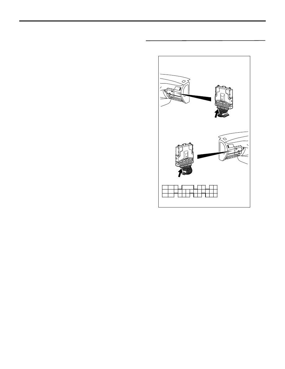
STEP 22. Connector check: C-121 engine-ECU
connector.
Q: Is the check result normal?
YES :
Check intermediate connectors A-29*
1
or
C-31*
2
, and repair if necessary. If
intermediate connectors are normal, check
and repair harness between A-07X (terminal
No. 3) condenser fan relay (high) connector
and C-121 (terminal No. 30) engine-ECU
connector.
• Check power supply for open circuit
and damage.
NO :
Repair or replace the connector.
STEP 23. Perform voltage measurement at A-34
condenser fan motor connector.
• Disconnect connector, and measure at harness
side.
• Disconnect C-121 engine-ECU connector, and
earth terminal No. 30.
• Ignition switch: "ON"
AK501995
2
3
4
5
6
7
8
9
11
12
13
14
15
16
17
18
19
20
30
21
22
23
24
25
26
27
28
29
31
32
33
34
35
1
10
AB
Connector: C-121
C-121 (GR)
C-121 (GR)
Harness side connector
<L. H. drive vehicles>
<R. H. drive vehicles>
AK305267
2
1
3
4
A-07X
Connector: A-07X
AB
Harness side
connector
Relay box’s
triangle marks
AK305266
1
2
A-34(B)
AB
Harness side
connector
Connector: A-34
AK305267
2
1
3
4
A-07X
Connector: A-07X
AB
Harness side
connector
Relay box’s
triangle marks
AK501995
2
3
4
5
6
7
8
9
11
12
13
14
15
16
17
18
19
20
30
21
22
23
24
25
26
27
28
29
31
32
33
34
35
1
10
AB
Connector: C-121
C-121 (GR)
C-121 (GR)
Harness side connector
<L. H. drive vehicles>
<R. H. drive vehicles>

TROUBLESHOOTING
MULTIPORT FUEL INJECTION (MPI)
13A-340
• Voltage between terminal No. 2 and earth.
OK: System voltage
Q: Is the check result normal?
YES :
Go to Step 24 .
NO :
Check intermediate connectors A-29*
1
or
C-31*
2
, and repair if necessary. If
intermediate connectors are normal, check
and repair harness between A-07X (terminal
No. 3) condenser fan relay (high) connector
and C-121 (terminal No. 30) engine-ECU
connector.
• Check power supply for open circuit
and damage.
STEP 24. Connector check: A-34 condenser fan
motor connector.
Q: Is the check result normal?
YES :
Go to Step 25 .
NO :
Repair or replace the connector.
STEP 25. Check harness between A-07X
(terminal No. 3) condenser fan relay (high)
connector and C-121 (terminal No. 30)
engine-ECU connector.
NOTE: Before checking harness, check intermediate
connector A-29*
1
or C-31*
2
, and repair if necessary.
• Check output line for damage.
Q: Is the check result normal?
YES :
Go to Step 26 .
NO :
Repair the damaged harness wire.
AK305266
1
2
A-34(B)
AB
Harness side
connector
Connector: A-34
AK305267
2
1
3
4
A-07X
Connector: A-07X
AB
Harness side
connector
Relay box’s
triangle marks
AK501995
2
3
4
5
6
7
8
9
11
12
13
14
15
16
17
18
19
20
30
21
22
23
24
25
26
27
28
29
31
32
33
34
35
1
10
AB
Connector: C-121
C-121 (GR)
C-121 (GR)
Harness side connector
<L. H. drive vehicles>
<R. H. drive vehicles>

TROUBLESHOOTING
MULTIPORT FUEL INJECTION (MPI)
13A-341
STEP 26. Connector check: A-35 condenser fan
motor connector.
Q: Is the check result normal?
YES :
Go to Step 27 .
NO :
Repair or replace the connector.
STEP 27. Perform resistance measurement at
A-35 condenser fan motor connector.
• Disconnect connector, and measure at harness
side.
• Resistance between terminal No. 2 and earth.
OK: 2
Ω or less
Q: Is the check result normal?
YES :
Replace the engine-ECU.
NO :
Repair the damaged harness wire.
Inspection Procedure 27: A/C Switch System
AK305443
1
2
A-35(GR)
AB
Harness side
connector
Connector: A-35
AK305443
1
2
A-35(GR)
AB
Harness side
connector
Connector: A-35
AK501832
80
87
81
94
85
82
84
93
86
98
99
74
92
73
83
88
91
95
97
96
100
89
78
71
90
76 77
75
72
79
P
Engine-ECU
83
A/C-ECU
A/C Switch circuit
C-117
(MU803783)
AB
Wire colour code
B: Black LG: Light green G: Green L: Blue W: White Y: Yellow SB: Sky blue BR: Brown O: Orange GR: Gray
R: Red P: Pink V: Violet PU: Purple
TROUBLESHOOTING
MULTIPORT FUEL INJECTION (MPI)
13A-342
OPERATION
• The battery voltage is applied to the engine-ECU
(terminal No. 83) from the A/C-ECU (terminal No.
1).
FUNCTION
• When the A/C switch is in "ON" position, A/C
switch ON signal is inputted to the engine-ECU
from the A/C-ECU. In response to the signal, the
engine-ECU controls the A/C compressor relay.
PROBABLE CAUSES
• Failed A/C
• Failed A/C system
• Open/short circuit in A/C circuit or loose connec-
tor contact
• Failed engine-ECU
DIAGNOSIS PROCEDURE
STEP 1. Perform voltage measurement at C-117
engine-ECU connector.
• Measure engine-ECU terminal voltage.
• Engine: Idling
• A/C set temperature:
Maximum Cool when temperature in cabin is
25
°C or more
Maximum Hot when temperature in cabin is 25
°C
or less
• Voltage between terminal No. 83 and earth.
OK:
System voltage (when A/C is ON)
0.5 V or less (when A/C is OFF)
Q: Is the check result normal?
YES :
Go to Step 2 .
NO :
Check A/C system (Refer to GROUP 55
−
Troubleshooting
− Check Chart for Trouble
AK501996
80
87
81
94
85
82
84
93
86
98
99
74
92
73
83
88
91
95
97 96
100
89
78
71
90
76
77
75
72
79
AB
Connector: C-117
C-117 (GR)
C-117 (GR)
Harness side connector
<L. H. drive vehicles>
<R. H. drive vehicles>
Нет комментариевНе стесняйтесь поделиться с нами вашим ценным мнением.
Текст