Mitsubishi Lancer Evolution IX. Manual — part 88
CYLINDER HEAD AND VALVES
ENGINE OVERHAUL
11B-43
REMOVAL SERVICE POINTS
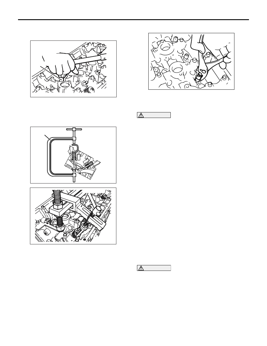
<<A>> CYLINDER HEAD BOLT REMOVAL
Use the special tool Cylinder head bolt wrench
(MB991654) to loosen the cylinder head bolts.
<<B>> RETAINER LOCK REMOVAL
Compress the valve spring using the special tool
Valve spring compressor (MD998735 or MD998772),
then remove the retainer lock.
NOTE: Store removed valves, springs and other
parts, after putting to each of them a tag that identi-
fies its cylinder No. or installation location.
<<C>> VALVE STEM SEAL REMOVAL
Do not reuse removed valve stem seal.
<<D>> VALVE HANDLING PRECAUTIONS
WARNING
Sodium reacts violently with water or mois-
ture generation heat and liberating hydro-
gen. It must be handled with utmost care
because otherwise the following dangerous
conditions may result:
•
Loss of eyesight if sodium gets in eyes.
•
Burns if sodium contacts skin.
•
Fire hazard.
1. Handling of Sodium-filled Exhaust Valves
(1) Sodium-filled exhaust valves are not
dangerous and may be handled in the same
way as ordinary valves unless they are
broken.
(2) Never try to break the valves and expose
sodium to the air.
(3) When worn exhaust valves are to be
discarded, have them disposed of by a
salvage company equipped with special
disposal system, notifying them that the valves
contain sodium.
(4) Should the exhaust valves be broken,
neutralize sodium using the method described
below, and discard the valves in the same way
as ordinary valves.
CAUTION
• Do not let the solution contact the eyes or the
skin.
• Should it get in the eyes, immediately flush
them with clean water thoroughly, and receive
medical attention. When it contacts he skin,
wash with ample amounts of clean water.
AK202723
MB991654
AE
AK202873
MD998735
AD
AK202742
MD998772
AD
AK304633

CYLINDER HEAD AND VALVES
ENGINE OVERHAUL
11B-44
2. How to Neutralize Sodium
(1) Place a container filled with more than 10 litres
of water in a well ventilated large space.
(2) Wear rubber gloves and goggles, and carefully
take out broken valves from the cylinder head.
CAUTION
• Valves must be neutralized one at a time.
• Put a valve in the container only after sodium
in the preceding one has completely reacted
with water.
(3) Put a broken valves in the water-filled
container and quickly get away from the
container at least 2 or 3 m.
(4) Keep fire away from the container during the
neutralization. The resulting hydrogen gas is
highly explosive.
NOTE: The reaction occurs when water enters
the cavity in he valve. Hydrogen gas may be
trapped inside the valve, temporarily blocking
the water passage. In such a case, wait until
hydrogen gas in released and remaining
sodium reacts with water.
(5) After the neutralization of sodium, water in the
container contains sodium hydroxide and is
highly alkaline. The water solution should be
disposed of according to local regulations.
INSTALLATION SERVICE POINTS
>>A<< VALVE STEM SEAL INSTALLA-
TION
CAUTION
The special tool must always be used when
installing the valve stem seal. Improper installa-
tion could result in oil leaks past the valve guide.
1. Install the valve spring seat.
2. Install the valve.
3. Apply a thin coat of engine oil to a new valve stem
seal.
4. Use the special tool Valve stem seal installer
(MD998737) to install the stem seal on the valve
guide. Use the stem of the valve to guide the stem
seal.
NOTE: Do not confuse the stem seals for intake
valves with those for exhaust valves.
>>B<< VALVE SPRING INSTALLATION
Install the valve spring whose small diameter is
shown from the rocker arm side.
AK304485
MD998737
AC
AK304538AB
Intake valve stem seal
Colour: Gray
Exhaust valve stem seal
Colour: Grayish green
AK305040AB
Small diameter

CYLINDER HEAD AND VALVES
ENGINE OVERHAUL
11B-45
>>C<< RETAINER LOCK INSTALLATION
Compress the valve spring using the special tool
Valve spring compressor (MD998735 or MD998772),
then install the retainer lock.
>>D<< CYLINDER HEAD BOLT
INSTALLATION
1. When reusing a cylinder head bolt, check that its
nominal length (shank length) is not greater than
the limit. If the limit is exceeded, replace the bolt.
Limit: 99.4 mm
2. Apply engine oil to the threads and washer of the
bolt.
3. Tighten the bolts to 78
± 2 N⋅m in the indicated
sequence.
NOTE: Use the special tool Cylinder head bolt
wrench (MB991654) to tighten the bolts.
4. Loosen all the bolts completely.
5. Tighten the bolts again to a torque of 20
± 2 N⋅m
in the indicated sequence.
CAUTION
• If the tightening angle is smaller than 90°,
proper fastening performance could not be
assured. Be sure to respect that angle.
• If the bolt is tightened to an angle greater than
the specified angle, loosen the bolt com-
pletely and then retighten it beginning with
the first step.
6. Make paint marks on each bolt’s head and on the
cylinder head.
7. Turn the bolts 90
° in the tightening direction and in
the indicated sequence.
AK202873
MD998735
AD
AK202742
MD998772
AD
AK300591AB
Shank length
AK202723
MB991654
AE
1
3
9
6
8
2
5
7
4
10
AK202806
Timing belt side
AB
AK202720
Paint marks
90˚
90˚
AB

CYLINDER HEAD AND VALVES
ENGINE OVERHAUL
11B-46
8. Give another 90
° turn in the tightening direction to
each bolt, making sure that the paint mark on the
bolt head and that on the cylinder head are on the
same line.
INSPECTION
M1113007000981
CYLINDER HEAD
1. Before cleaning the cylinder head, check it for
traces of water and gas leakage and for cracks
and any other damage.
2. Thoroughly remove oils, scale, sealants, carbon
and other contamination. Clean the oil passages,
then check using compressed air that they are not
blocked.
CAUTION
The thickness of the metal that can be removed
by grinding from both the cylinder head and the
mating cylinder block is limited to 0.2 mm in
total.
3. Check the cylinder head gasket surface for warp
using a straightedge and thickness gauge.
If the surface is warped beyond the limit, grind the
surface for rectification.
Gasket surface warp
Standard value: Less than 0.05 mm
Limit: 0.2 mm
Grinding limit: 0.2 mm
Cylinder head height (standard value for new
part): 131.9
− 132.1 mm
VALVES
1. Check the valve face for correct contact with the
seat. Reface the valve if the contact is partial or
one sided.
2. Measure the margin.
Replace the valve if its margin is smaller than the
limit.
Standard values:
Intake 1.0 mm
Exhaust 1.5 mm
Limits:
Intake 0.5 mm
Exhaust 1.0 mm
3. Measure the total length of the valve.
Replace the valve if the length is less than the
limit.
Standard values:
Intake 109.5 mm
Exhaust 109.7 mm
Limits:
Intake 109.0 mm
Exhaust 109.2 mm
AK202724
AK300593AB
Margin
Contact
(Should be at
centre of face)
AK202876
Total length
AB
Нет комментариевНе стесняйтесь поделиться с нами вашим ценным мнением.
Текст