Mitsubishi Lancer Evolution IX. Manual — part 625
TROUBLESHOOTING
SUPPLEMENTAL RESTRAINT SYSTEM (SRS)
52B-13
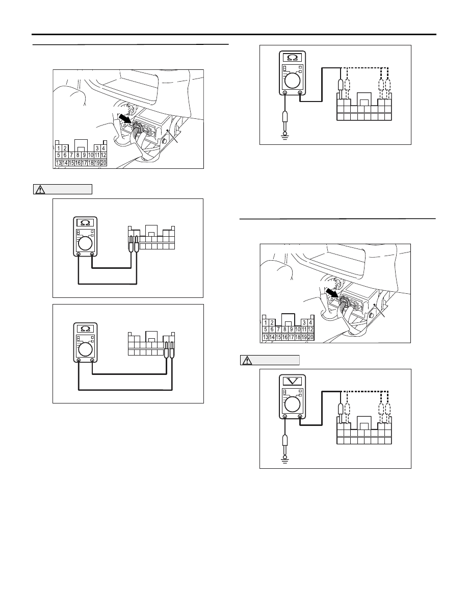
Step 2. Resistance measurement at the SRS-ECU
connector C-12.
(1) Disconnect SRS-ECU connector C-12.
CAUTION
Do not insert a test probe into the terminal from
its front side directly as the connector contact
pressure may be weakened.
(2) Take the measurements below at harness-side
connector C-12.
• Resistance between terminals 1 and 2 as well
as 3 and 4.
NG: 2 ohms or less (short circuit) or 2
megaohms or more (open circuit)
• Continuity between terminals 1, 2, 3, 4 and
body earth
OK: No continuity
Q: Is the check result satisfactory?
YES :
Go to Step 3.
NO :
Go to Step 4.
Step 3. Voltage measurement at the SRS-ECU
connector C-12.
(1) Disconnect SRS-ECU connector C-12.
CAUTION
Do not insert a test probe into the terminal from
its front side directly as the connector contact
pressure may be weakened.
(2) Take the measurements below at harness-side
connector C-12.
• Voltage between terminals 1, 2, 3, 4 and body
earth
OK: 0V
Q: Is the check result satisfactory?
YES :
Go to Step 5.
NO :
Go to Step 4.
AC101950AJ
SRS-ECU
Harness side
connector
(rear view)
C-12 (Y)
Connector: C-12
AC100338
AC103684
1314151617181920
5 6 7 8 9 101112
1 2
3 4
AC103683 AK
C-12 Harness side
(Rear View)
AC100338
1314151617181920
5 6 7 8 9 101112
1 2
3 4
AC103684 AK
C-12 Harness side
(Rear View)
AC103372
4
1
2
3
5
7
6
8
16
15
14
13
12
11
10
9
20
19
18
17
AI
C-12 Harness side
(Rear View)
AC101950AJ
SRS-ECU
Harness side
connector
(rear view)
C-12 (Y)
Connector: C-12
4
1
2
3
5
7
6
8
16
15
14
13
12
11
10
9
20
19
18
17
AC210613
C-12 Harness side
(Rear View)
AB

TROUBLESHOOTING
SUPPLEMENTAL RESTRAINT SYSTEM (SRS)
52B-14
Step 4. Check the wiring harness between the
right front impact sensor connector A-37
(terminals 1 and 2) and SRS-ECU connector C-12
(terminals 1 and 2) as well as between left front
impact sensor connector A-33 (terminals 1 and 2)
and SRS-ECU connector C-12 (terminals 3 and 4).
NOTE:
AC310431
Connector: A-37 <LHD>
AF
Harness side
(front view)
A-37 (Y)
2
1
AC310433
Connector: A-37 <RHD>
AE
Harness side
(front view)
A-37 (Y)
2
1
AC101950AJ
SRS-ECU
Harness side
connector
(rear view)
C-12 (Y)
Connector: C-12
AC310542
Connectors: A-33 <LHD>
AE
A-33 (Y)
Harness side
(front view)
2
1
AC310475
Connector: A-33 <RHD>
AD
A-33 (Y)
Harness side
(front view)
2
1
AC310452
AW
Connector: C-111
<LHD>
AC310456
Connector: C-111
AT
<RHD>
AC310446
Connector: C-129 <LHD>
BD

TROUBLESHOOTING
SUPPLEMENTAL RESTRAINT SYSTEM (SRS)
52B-15
Prior to the wiring harness inspection, check interme-
diate connectors C-111 and C-129, and repair if nec-
essary.
• Check the front impact sensor output line for
open or short circuit.
Q: Is the check result satisfactory?
YES :
Go to Step 4.
NO :
Repair the wiring harness.
Step 5. Check whether the diagnosis code is
reset.
Check again if the diagnosis code is set.
(1) Erase the diagnosis code.
(2) Turn the ignition switch to the "ON" position.
(3) Check if the diagnosis code is set.
(4) Turn the ignition switch to the "LOCK" (OFF)
position.
Q: Is diagnosis code 1A, 1B, 1C, 1D, 2A, 2B, 2C or 2D
set?
YES :
Replace the SRS-ECU (Refer to
).
NO :
The procedure is complete. (If no
malfunctions are found in all steps, an
intermittent malfunction is suspected. Refer
to GROUP 00
− How to Use
Troubleshooting/Inspection Service Points
).
Code No.14: Analogue G-sensor malfunction
Code No.15: Safing G-sensor (for frontal collision) short-circuited
Code No.16: Safing G-sensor (for frontal collision) open-circuited
Code No.31: SRS-ECU capacitor circuit voltage too high
Code No.32: SRS-ECU capacitor circuit voltage too low
Code No.45: SRS-ECU non-volatile memory (EEPROM) and A/D converter system
Code No.51: Driver's air bag squib activating circuit short-circuited
Code No.52: Driver's air bag squib activating circuit open-circuited
Code No.54: Passenger's (front) air bag squib activating circuit short-circuited
Code No.55: Passenger's (front) air bag squib activating circuit open-circuited
Code No.56: Driver’s seat belt pre-tensioner activating circuit short-circuited
Code No.57: Driver’s seat belt pre-tensioner activating circuit open-circuited
Code No.58: Passenger’s (front) seat belt pre-tensioner activating circuit short-circuited
Code No.59: Passenger’s (front) seat belt pre-tensioner activating circuit open-circuited
AC310454
Connector: C-129 <RHD>
AV

TROUBLESHOOTING
SUPPLEMENTAL RESTRAINT SYSTEM (SRS)
52B-16
DIAGNOSIS CODE SET CONDITIONS
These diagnosis codes are set when a fault is
detected in the SRS-ECU. The most likely causes for
this code to be set are shown in the table below:
PROBABLE CAUSE
Malfunction of the SRS-ECU
DIAGNOSIS PROCEDURE
Replace the SRS-ECU (Refer to
Code No.
Part/Circuit integral to
SRS-ECU
Trouble causes
14
Analog G-sensor
• When the analog G-sensor is not operating
• When the characteristics of the analog G-sensor are
abnormal
• When the output from the analog G-sensor is
abnormal
15
Safing G-sensor (for frontal
collision)
• Short circuit in the safing G-sensor
16
• Open circuit in the safing G-sensor
31
Capacitor circuit
• Voltage at the capacitor terminal is higher than the
specified value for five seconds or more
32
• Voltage at the capacitor terminal is lower than the
specified value for five seconds or more (This is not
detected if diagnosis code No.41 or 42 indicating
battery positive voltage drop has been output).
45
Non-volatile memory (EEPROM)
and A/D converter
• When the non-volatile memory (EEPROM) and A/D
converter system are abnormal
51
Driver's air bag module (squib
ignition drive circuit)
• Short circuit in the squib ignition drive circuit
52
• Open circuit in the squib ignition drive circuit
54
Passenger's (front) air bag
module (squib ignition drive
circuit)
• Short circuit in the squib ignition drive circuit
55
• Open circuit in the squib ignition drive circuit
56
Driver’s seat belt pre-tensioner
(squib ignition drive circuit)
• Short circuit in the squib ignition drive circuit
57
• Open circuit in the squib ignition drive circuit
58
Passenger’s (front) seat belt
pre-tensioner (squib ignition drive
circuit)
• Short circuit in the squib ignition drive circuit
59
• Open circuit in the squib ignition drive circuit
Нет комментариевНе стесняйтесь поделиться с нами вашим ценным мнением.
Текст