Mitsubishi Lancer Evolution IX. Manual — part 489
ON-VEHICLE SERVICE
SERVICE BRAKES
35A-11
BRAKE DISC THICKNESS CHECK
M1351002400469
CAUTION
Take care not to contact the parts or tools to the
caliper because the paint of caliper will be
scratched. And if there is brake fluid on the cali-
per, wipe it off quickly.
ACX00668AB
1. Using a micrometer, measure disc thickness at
eight positions, approximately 45 degrees apart
and 10 mm from the outer edge of the disc.
Standard value:
<Front> 32.0 mm
<Rear> 22.0 mm
Minimum limit:
<Front> 29.8 mm
<Rear> 20.4 mm
NOTE: Thickness variation (at least 8 positions)
should not be more than 0.015 mm.
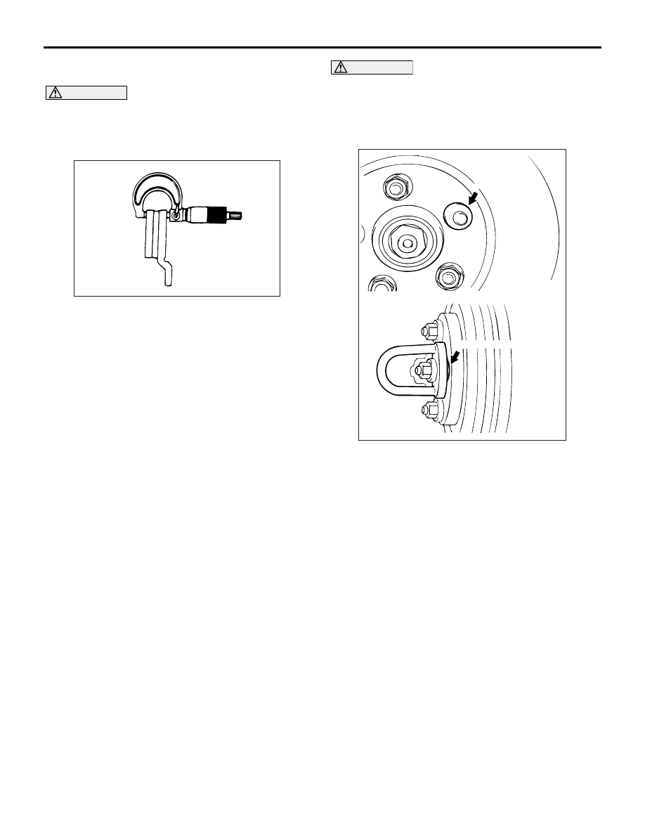
CAUTION
• After a new brake disc is installed, always
grind the brake disc with on-the-car type
brake lathe. If this step is not carried out, the
brake disc run-out exceeds the specified
value, resulting in judder.
•
AC006226 AB
M12 flat washer
M12 flat washer
When the on-the-car type lathe is used, first
install a M12 flat washer on the stud bolt in
the brake disc side according to the figure,
and then install the adapter. If the adapter is
installed with M12 flat washer not seated, the
brake disc rotor may be deformed, resulting
in inaccurate grinding.
• Grind the brake disc with all wheel nuts diag-
onally and equally tightened to the specified
torque 100 N
⋅m. When all numbers of wheel
nuts are not used, or the tightening torque is
excessive or not equal, the brake disc rotor or
drum may be deformed, resulting in judder.
2. If the disc thickness is less than the limits, replace
it with a new one. If thickness variation exceeds
the specification, turn rotor with an on-the-car type
brake lathe ("Accuturn-8750" or equivalent).
If the calculated final thickness after turning the
rotor is less than the standard value, replace the
disc.

ON-VEHICLE SERVICE
SERVICE BRAKES
35A-12
BRAKE DISC RUN-OUT CHECK AND
CORRECTION
M1351009400534
CAUTION
Take care not to contact the parts or tools to the
caliper because the paint of caliper will be
scratched. And if there is brake fluid on the cali-
per, wipe it off quickly.
1. Remove the brake assembly, and then hold it with
wire.
2. Temporarily install the disc with the hub nut.
ACX00669AB
3. Place a dial gauge approximately 5 mm from the
outer circumference of the brake disc, and
measure the run-out of the disc.
Limit: 0.03 mm
AC210711AB
Chalk marks
4. If the brake disc run-out exceeds the limit, correct
it as follows:
(1) Chalk phase marks on the wheel stud and the
brake disc, which run-out is excessive as
shown.
AC102438 AC
<Front>
AC205869AC
<Rear>
(2) Remove the brake disc. Then place a dial
gauge as shown, and measure the axial play
by pushing and pulling the wheel hub.
Limit: 0.05 mm
(3) If the axial play exceeds the limit, disassemble
the hub and knuckle assembly to check each
part.
(4) If the axial play does not exceed the limit,
dephase the brake disc and secure it. Then
recheck the brake disc run-out.

ON-VEHICLE SERVICE
SERVICE BRAKES
35A-13
CAUTION
• After a new brake disc is installed, always
grind the brake disc with on-the-car type
brake lathe. If this step is not carried out, the
brake disc run-out exceeds the specified
value, resulting in judder.
•
AC006226 AB
M12 flat washer
M12 flat washer
When the on-the-car type lathe is used, first
install a M12 flat washer on the stud bolt in
the brake disc side according to the figure,
and then install the adapter. If the adapter is
installed with M12 flat washer not seated, the
brake disc rotor may be deformed, resulting
in inaccurate grinding.
• Grind the brake disc with all wheel nuts diag-
onally and equally tightened to the specified
torque 100 N
⋅m. When all numbers of wheel
nuts are not used, or the tightening torque is
excessive or not equal, the brake disc rotor or
drum may be deformed, resulting in judder.
5. If the run-out cannot be corrected by changing the
phase of the brake disc, replace the brake disc or
grind it with the on-the-car type brake lathe
("Accuturn-8750" or equivalent).
BRAKE PEDAL
SERVICE BRAKES
35A-14
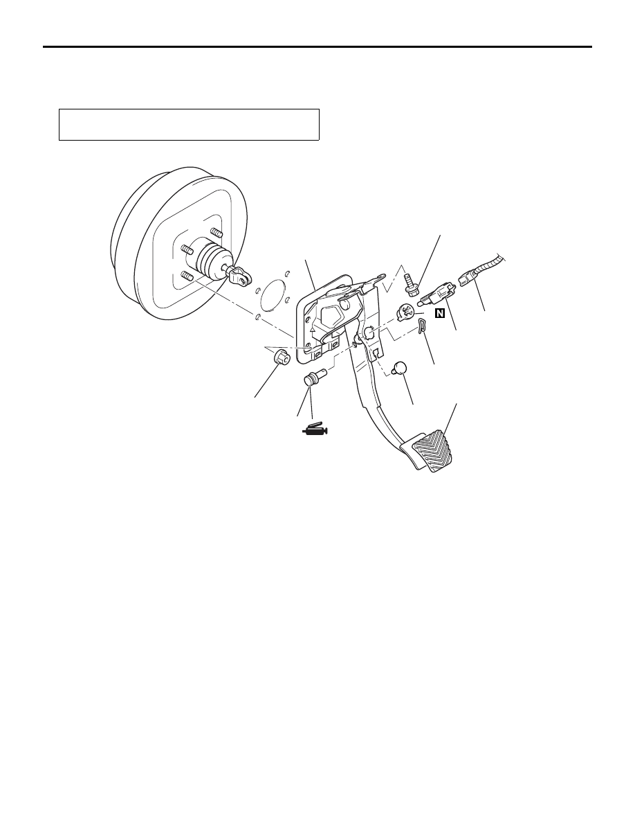
BRAKE PEDAL
REMOVAL AND INSTALLATION
M1351003400473
Post-installation Operation
• Brake Pedal Adjustment (Refer to
AC211554 AB
12 ± 2 N·m
14 ± 3 N·m
6
1
2
3
4
7
8
5
Removal steps
1. Harness connector
2. Stoplamp switch
3. Brake pedal clip
4. Brake pedal stopper
5. Brake booster pin
6. Brake pin assembly
7. Brake pedal pad
>>
A
<< 8. Brake pedal assembly
Removal steps (Continued)
Нет комментариевНе стесняйтесь поделиться с нами вашим ценным мнением.
Текст