Mitsubishi Lancer Evolution IX. Manual — part 243
SYMPTOM PROCEDURES
SMART WIRING SYSTEM (SWS) USING SWS MONITOR
54C-231
FOG LAMP
INSPECTION PROCEDURE J-1: The rear fog lamp do not illuminate normally.
CAUTION
Whenever the ECU is replaced, ensure that the
input and output signal circuits are normal.
Wire colour code
B : Black LG : Light green G : Green L : Blue W : White Y : Yellow SB : Sky blue
BR : Brown O : Orange GR : Gray R : Red P : Pink V : Violet
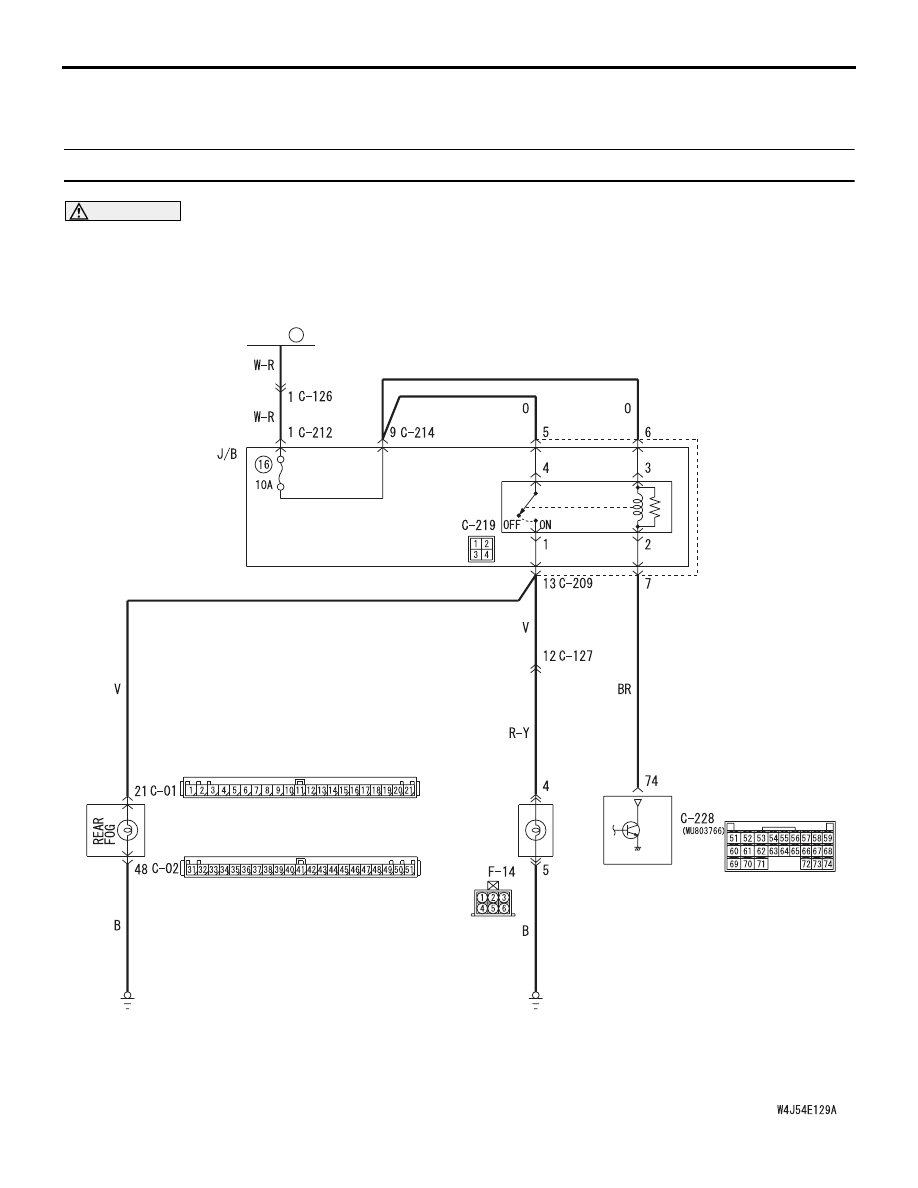
ETACS-ECU
FUSIBLE
LINK
1
COMBINATION
METER
REAR
COMBINATION
LAMP
(REAR FOG)
REAR
FOG
LAMP
RELAY
Rear Fog Lamp Circuit <LHD>

SYMPTOM PROCEDURES
SMART WIRING SYSTEM (SWS) USING SWS MONITOR
54C-232
OPERATION
The ETACS-ECU operates this function in accord-
ance with the input signals below.
• Tail lamp switch
• Headlamp switch
• Rear fog lamp switch
If the rear fog lamps do not illuminate normally, these
input signal circuit(s) or the ETACS-ECU may be
defective.
Wire colour code
B : Black LG : Light green G : Green L : Blue
W : White Y : Yellow SB : Sky blue BR : Brown
O : Orange GR : Gray R : Red P : Pink V : Violet
COMBINATION
METER
REAR
COMBINATION
LAMP
(REAR FOG)
REAR FOG
LAMP RELAY
ETACS-
ECU
FUSIBLE
LINK
1
Rear Fog Lamp Circuit <RHD>

SYMPTOM PROCEDURES
SMART WIRING SYSTEM (SWS) USING SWS MONITOR
54C-233
POSSIBLE CAUSES
• Malfunction of the column switch
• Malfunction of the fog lamp switch
• Malfunction of the ETACS-ECU
• Damaged harness wires and connectors
DIAGNOSIS PROCEDURE
Step 1. Check that the tail lamps and headlamps
operate.
Check that the tail lamps and headlamps illuminate
normally.
Q: Is the check result normal?
YES :
Go to Step 2.
NO :
Check the tail lamps and the headlamps
(Refer to trouble symptom chart
).
Step 2. ECU check by using the SWS monitor.
Check that the power supply and earth lines to the
column switch (column-ECU), the ETACS-ECU and
the front-ECU and the SWS communication lines are
normal.
• Ignition switch: OFF
ECUS TO BE CHECKED
• COLUMN ECU
• ETACS ECU
• FRONT ECU
OK: "OK" is displayed for all the items
Q: Is the check result normal?
"OK" is displayed for all the items :
Go to Step 3.
"NG" is displayed on the "COLUMN ECU" menu. :
Refer to Inspection Procedure A-2
"Communication with the column switch
(column-ECU) is not possible
."
"NG" is displayed on the "ETACS ECU" menu. :
Refer to Inspection Procedure A-3
"Communication with the ETACS-ECU is
not possible
"NG" is displayed on the "FRONT ECU" menu. :
Refer to Inspection Procedure A-4
"Communication with the front-ECU is not
possible
."
Step 3. Function diagnosis by using the SWS
monitor.
Check the SWS communication signal, which are
related to the fog lamps.
<Selected item> LIGHTING - REAR FOG LAMP
• Ignition switch: ON
• Lighting switch: "TAIL" or "HEAD"
• Rear fog lamp switch: ON
OK: Normal conditions are displayed for all
the items.
Q: Is the check result normal?
Normal conditions are displayed for all the items. :
Go to Step 4.
Normal condition is not displayed for item 00 or 01.
:
Refer to Inspection Procedure L-4 "The
column switch (lighting and turn-signal lamp
switch) signal is not received
Step 4. Pulse check.
Check the input signals below, which are related to
the rear fog lamps.
OK: The M.U.T.-II/III sounds or the voltmeter
needle fluctuates.
Q: Is the check result normal?
All the signals are received normally. :
Go to Step
5.
The ignition switch (IG1) signal is not received. :
Refer to Inspection Procedure L-2 "The
ignition switch (IG1) signal is not received
."
The rear fog lamp switch signal is not received. :
Refer to Inspection Procedure L-8 "The rear
fog lamp switch signal is not received
."
Item No. Item name
Normal condition
Item 00
HEADLAMP SW
ON when the
lighting switch is at
HEAD
Item 01
TAIL LAMP SW
ON when the
lighting switch is at
TAIL
System switch
Check condition
Ignition switch (IG1)
When turned from ACC
to ON
Rear fog lamp switch
When the rear fog lamp
switch is turned from off
to on
SYMPTOM PROCEDURES
SMART WIRING SYSTEM (SWS) USING SWS MONITOR
54C-234
Step 5. Connector check: C-219 rear fog lamp
relay connector
Q: Is the check result normal?
YES :
Go to Step 6.
NO :
Repair the defective connector.
Step 6. Check the rear fog lamp relay.
Refer to GROUP 54A
− Rear fog lamp
.
Q: Is the check result normal?
YES :
Go to Step 7.
NO :
Replace the rear fog lamp relay.
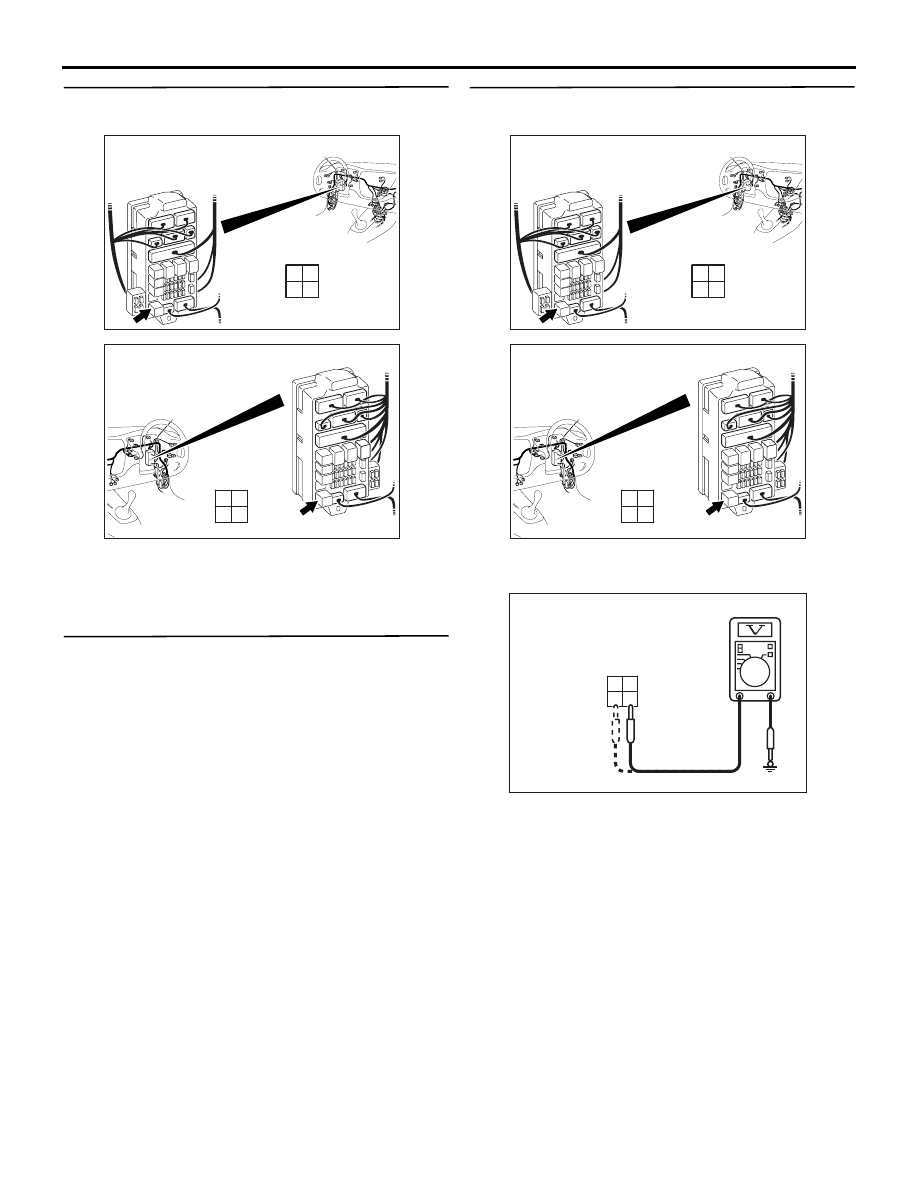
Step 7. Voltage measurement at the C-219 rear
fog lamp relay connector
(1) Remove the rear fog lamp relay, and measure at
the junction block side.
(2) Check the voltage between the rear fog lamp
relay connector and body earth.
• Voltage between C-219 rear fog lamp relay
connector terminal No.3 and body earth
• Voltage between C-219 rear fog lamp relay
connector terminal No.4 and body earth
OK: System voltage
Q: Is the check result normal?
YES :
Go to Step 9.
NO :
Go to Step 8.
AC310448
Junction block (front view)
Connector: C-219
AN
<LHD>
Junction block side
3
1
2
4
AC310458
Junction block (front view)
Connector: C-219
AK
<RHD>
Junction block side
3
1
2
4
AC310448
Junction block (front view)
Connector: C-219
AN
<LHD>
Junction block side
3
1
2
4
AC310458
Junction block (front view)
Connector: C-219
AK
<RHD>
Junction block side
3
1
2
4
AC301541HC
Connector C-219
(Junction block side)
4
2 1
3
Нет комментариевНе стесняйтесь поделиться с нами вашим ценным мнением.
Текст