Mitsubishi Lancer Evolution IX. Manual — part 75
HOW TO READ WIRING DIAGRAMS
GENERAL <ELECTRICAL>
00E-3
HOW TO READ CONFIGURATION
DIAGRAMS
M1001006400238
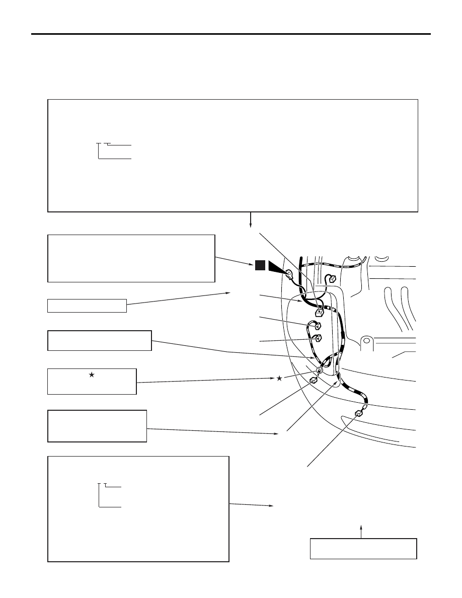
The wiring harness diagrams clearly show the connector locations and harness routings at each site on
actual vehicles.
AC208446
Denotes connector No.
The same connector No. is used throughout the circuit diagrams to facilitate connector location search.
The first alphabetical symbol indicates the location site of the connector and a number that follows is the unique number.
Numbers are usually assigned to part in clockwise order on the diagram.
Example: A-19
Number specific to connector (serial number)
Connector location site symbol
A: Engine compartment
B: Engine and transmission
C: Dash panel
D: Floor and roof
E: Door
F: Trunk
Denotes earth point.
Same earth number is used throughout circuit
diagrams to facilitate search of earth point.
Refer to GROUP 70 COMPONENT LOCATIONS
- EARTH MOUNTING LOCATIONS
for details of earth points.
Denotes the colour of the tube
(If not specified, it is black).
R: Red
Y: Yellow
The number of connector pins and the connector colour
(except milk white)* are shown for ease of retrieval.
Example: (2-B)
Connector colour
(milk white if no colour is indicated)
Number of connector pins
*: Typical connector colours
B: Black
BR: Brown
Y: Yellow
V: Violet
L: Blue
O: Orange
G: Green
GR: Grey
R: Red
None: Milk white
A-15 (2) Fog lamp (RH)
A-16 (2-GR) Horn (LO)
A-17 (2-B) Headlamp (RH)
A-18 (2-B) Windshield washer motor
A-19 (2-GR) Dual pressure switch
Indicates the device to which the
connector is connected.
The mark shows the
standard mounting position
of wiring harness.
AQ
A-17
A-16
A-15
A-18
A-19
Y
Denotes a section covered by a
corrugated tube.
Front
wiring
harness
(RH)
Denotes harness name.
1
HOW TO READ WIRING DIAGRAMS
GENERAL <ELECTRICAL>
00E-4
HOW TO READ CIRCUIT DIAGRAMS
M1001006500183
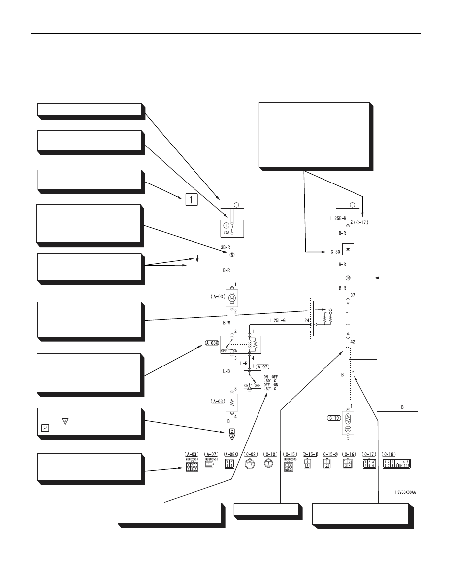
The circuit of each system from the fuse (or fusible link) to earth is shown. The power source is shown at the
top and the earth at the bottom to facilitate understanding of how the current flows. The circuit diagrams show
the state when switches are not operated.
AC502478
FUSIBLE
LINK
1
RELAY
BOX
HEATER
MOTOR
RELAY
SWITCH
RESISTOR
SENSOR
STARTING
SYSTEM
DIODE
FUSIBLE
LINK
2
ECU
Indicates power source.
Each circuit diagram consists of
block(s).
Indicates harness junction point
numbers for another system.
The number corresponds to the
junction point number indicated
on another circuit diagram.
Indicates the circuit name to be
connected. The arrow indicates
the current flow direction.
Indicates the power supply in
the control unit. If no voltage is
displayed, this indicates battery
positive voltage.
An "X" at the end of a connector
number indicates that the conn-
ector is connected to a central-
ized junction that is shown in the
section "Centralized Junction."
Indicates the connector symbol.
Connectors in the circuit diagram
are indicated in numerical order.
Indicates connector number.
The same number as used in the
wiring harness diagram.
Connector and connector numbers
are shown at the lower part of the
page.
Connector numbers not enclosed
by frame indicate the device incor-
porated into wiring harness.
Indicates that the diagram contin-
ues at which belongs to the
block in the same circuit.
AB
Indicates that terminal is conne-
cted via a plate in the relay box.
Indicates the operating conditions
of the engine coolant switch, etc.
Indicates shield wire.
One-directional arrow indicates
that current flows upwards.
AC209124
IGNITION
SWITCH (IG1)
RESISTOR
SOLENOID
VALVE
ASSEMBLY
SOLENOID
VALVE 1
SOLENOID
VALVE 2
SENSOR
MOTOR
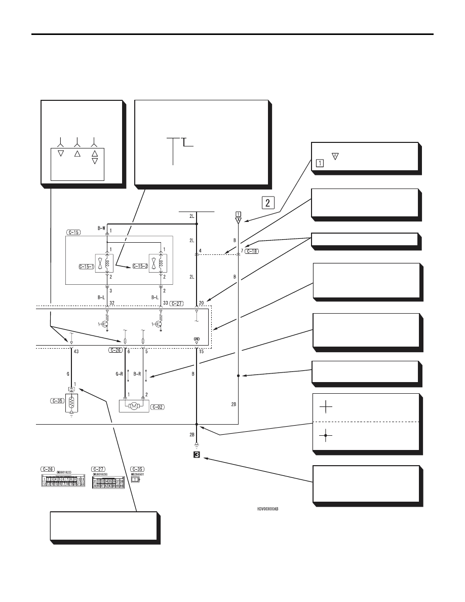
Indicates that the terminal is a
spare one if the device (sensor
in this case) is not provided.
Indicates representative vehicle
body earth point. (Same number
as that of earth point in
EARTHING LOCATION).
Indicates harness junction where
wire diameter or colour changes.
In case two or more connectors
are connected to the same de-
vice, the same connector are
shown by a broken line.
Indicates terminal number.
Indicates that these connectors
are the same intermediate
connectors.
Indicates input/output
to/from control unit
(current flow direction).
Input Output
Input/
output
Bi-directional arrow indicates
that current flows in both
directions due to control by an
ECU.
AC
Indicates a wiring connector which is inside
the equipment and which is not shown in
the wiring harness configuration diagram.
Example C-15-2
Indicates a connector
which is inside the
equipment, numbered
in order starting from 1.
Indicates the connector number shown in
the wiring harness configuration diagram.
Indicates intersections at
which the lead wires are
not connected.
Indicates intersections at
which the lead wires are
connected.
Indicates that the diagram comes
from which belongs to the
block in the same circuit.
HOW TO READ WIRING DIAGRAMS
GENERAL <ELECTRICAL>
00E-5
HOW TO READ WIRING DIAGRAMS
GENERAL <ELECTRICAL>
00E-6
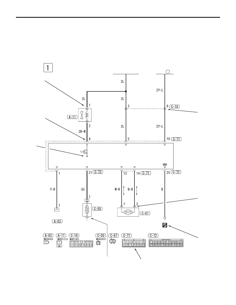
MARKINGS FOR CONNECTOR AND
EARTHING
M1001007900162
AC208460
IGNITION
SWITCH (IG1)
FUSIBLE
LINK
1
SOLENOID
VALVE
ECU
INSPECTION
CONNECTOR
SENSOR
MOTOR
AB
3
1
8
7
2
6
4
5
Нет комментариевНе стесняйтесь поделиться с нами вашим ценным мнением.
Текст