Mitsubishi Lancer Evolution IX. Manual — part 106
GENERAL DATA AND SPECIFICATIONS
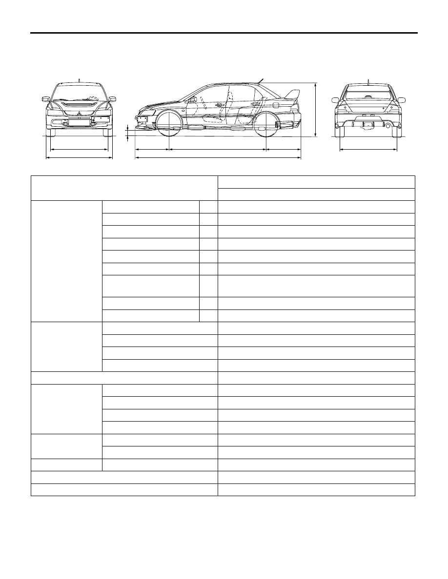
GENERAL
00-17
GENERAL DATA AND SPECIFICATIONS
M1001000901045
AC505135
1
2
7
3
4
6
5
8
9
AB
Items
CT9A
SJGFZL6/R6
Vehicle
dimensions mm
Front track
1
1,515
Overall width
2
1,770
Front overhang
3
930
Wheel base
4
2,625
Rear overhang
5
935
Overall length
6
4,490
Ground clearance
(unladen)
7
140
Overall height (unladen)
8
1,450
Rear track
9
1,515
Vehicle weight kg Kerb weight
1,465
Max. gross vehicle weight
1,885
Max. axle weight rating-front
1,015
Max. axle weight rating-rear
900
Seating capacity
5
Engine
Model code
4G63 DOHC-MIVEC with intercooler turbocharger
Total displacement mL
1,997
Maximum output kW/r/min
206/6,500
Maximum torque N
⋅m/r/min
355/3,500
Transmission
Model code
W6MAA
Type
6-speed manual
Fuel system
Fuel supply system
MPI
Maximum speed km/h
250
Minimum turning radius m
5.9
PRECAUTIONS BEFORE SERVICE
GENERAL
00-18
PRECAUTIONS BEFORE SERVICE
M1001000501058
SUPPLEMENTAL RESTRAINT SYSTEM
(SRS)
1. Items to review when servicing SRS:
1. Be sure to read GROUP 52B
− Supplemental
Restraint System (SRS). For safe operation,
please follow the directions and heed all
warnings.
2. Wait at least 60 seconds after disconnecting
the battery cable before doing any further
work. The SRS system is designed to retain
enough voltage to deploy the air bag even
after the battery has been disconnected. Seri-
ous injury may result from unintended air bag
deployment if work is done on the SRS sys-
tem immediately after the battery cable is dis-
connected.
3. Warning labels must be heeded when servic-
ing or handling SRS components. Warning
labels can be found in the following locations.
• Front impact sensor
• Hood
• Sun visor
• SRS-ECU
• Steering wheel
• Clock spring
• Steering joint cover
• Air bag module (Driver's and front passen-
ger's)
• Side-airbag module (Driver's side and
front passenger's side)
• Curtain air bag module (Driver's side and
front passenger's side)
• Side impact sensor
• Seat belt pre-tensioner
• Instrument panel
4. Always use the designated special tools and
test equipment.
5. Store components removed from the SRS in a
clean and dry place. The air bag module
should be stored on a flat surface and placed
so that the pad surface is facing upward. Do
not place anything on top of it.
6. Never attempt to disassemble or repair the
SRS components (SRS-ECU, air bag module
and clock spring).
7. Whenever you finish servicing the SRS,
check the SRS warning lamp operation to
make sure that the system functions properly.
8. Be sure to deploy the air bag before disposing
of the air bag module or disposing of a vehicle
equipped with an air bag (Refer to GROUP
52B
− Air Bag Module Disposal Procedures
2. Observe the following when carrying out opera-
tions on places where SRS components are
installed, including operations not directly related
to the SRS air bag.
1. When removing or installing parts, do not
allow any impact or shock to the SRS compo-
nents.
2. If heat damage may occur during paint work,
remove the SRS-ECU, the air bag module,
clock spring, the front impact sensor, the side
impact sensor, and the seat belt pre-ten-
sioner.
• SRS-ECU, air bag module, clock spring,
front impact sensor, the side impact sen-
sor: 93
°C or more
• Seat belt pre-tensioner: 90 °C or more
LEARNING PROCEDURE FOR IDLING IN
MPI ENGINE
PURPOSE
When the engine-ECU is replaced, or when the
learning value is initialized, the idling is not stabilized
because the learning value in MPI engine is not com-
pleted. In this case, carry out the learning method for
the idling through the following procedures.
LEARNING PROCEDURE
1. Start the engine and carry out the warm-up for the
engine coolant temperature to reach 80
°C or
more.
2. When the engine coolant temperature is 80
°C or
more, the warm-up is not needed if the ignition
switch is in "ON" position once.
3. Place the ignition switch in "LOCK" (OFF) position
and stop the engine.
4. After 10 seconds or more, start the engine again.
5. For 10 minutes, carry out the idling under the
condition shown below and then confirm the
engine has the normal idling.
• Transmission: Neutral
• Operation in ignition-related, fan and attach-
ments: Not to be operated
• Engine coolant temperature: 80°C or more

PRECAUTIONS BEFORE SERVICE
GENERAL
00-19
NOTE: When the engine stalls during the idling,
check the dirtiness (on the throttle valve) of the
throttle body and then perform the service from
Procedure 1 again.
SERVICING ELECTRICAL SYSTEM
CAUTION
Before connecting or disconnecting the negative
(
−) cable, be sure to turn off the ignition switch
and the lighting switch (If this is not done, there
is the possibility of semiconductor parts being
damaged).
AC300693
Before replacing a component related to the electri-
cal system and before undertaking any repair proce-
dures involving the electrical system, be sure to first
disconnect the negative (
−) cable from the battery in
order to avoid damage caused by short-circuiting.
APPLICATION OF ANTI-CORROSION
AGENTS AND UNDERCOATS
If oil or grease gets onto the oxygen sensor, it will
cause a drop in the performance of the sensor.
Cover the oxygen sensor with a protective cover
when applying anti-corrosion agents and undercoats.
PRE-INSPECTION CONDITION
"Pre-inspection condition" refers to the condition that
the vehicle must be in before proper engine inspec-
tion can be carried out. If you see the words "Set the
vehicle to the pre-inspection condition". In this man-
ual, it means to set the vehicle to the following condi-
tion.
• Engine coolant temperature 80 to 90°C
• Lamps, electric cooling fan and all accessories:
OFF
• M/T: Neutral
VEHICLE WASHING
AC300832AB
Approximately 40 cm
If high-pressure car-washing equipment or steam
car-washing equipment is used to wash the vehicle,
be sure to note the following information in order to
avoid damage to plastic components, etc.
• Spray nozzle distance: Approx. 40 cm or more
• Spray pressure: 3,900 kPa or less
• Spray temperature: 82°C or less
• Time of concentrated spray to one point: within
30 sec.

PRECAUTIONS BEFORE SERVICE
GENERAL
00-20
MULTI USE TESTER (M.U.T.-II/III) SUB
ASSEMBLY
AC300834AC
M.U.T.-II sub assembly
Rom pack
Refer to the "M.U.T.-II REFERENCE MANUAL",
"M.U.T.-II OPERATING INSTRUCTIONS" or
"M.U.T.-III OPERATING INSTRUCTIONS" for
instructions on handling the M.U.T.-II/III.
MB991910
MB991824
MB991827
MB991826
MB991911
MB991825
AC502279
Vehicle communication interface (V.C.I.)
M.U.T.-III sub assembly
M.U.T.-III USB cable
M.U.T.-III main harness A
M.U.T.-III main harness B
Do not used
M.U.T.-III measurement adapter
M.U.T.-III trigger harness
AC
Нет комментариевНе стесняйтесь поделиться с нами вашим ценным мнением.
Текст