Mitsubishi Lancer Evolution IX. Manual — part 415

TROUBLESHOOTING
MULTIPORT FUEL INJECTION (MPI)
13A-135
Code No. P0300: Random Cylinder Misfire Detected
OPERATION
• Refer to P0201 injector circuit
• Refer to P0202 injector circuit
• Refer to P0203 injector circuit
• Refer to P0204 injector circuit
FUNCTION
• If a misfire occurs while the engine is running, the
engine speed changes for an instant.
• The engine-ECU checks for such changes in
engine speed.
TROUBLE JUDGMENT
Check Conditions
• The engine speed is 500 − 6,500 r/min.
• The engine coolant temperature is −10°C or
higher.
• The barometric pressure is 76 kPa or more.
• The volumetric efficiency is 30 − 55%.
• The adaptive learning has been completed with
the vane that generates the crankshaft position
signals.
• During the engine operation except the shift
change or low speed driving and rapid accelera-
tion and deceleration, also intermittent operation
of air compressor (A/C: within the 3 seconds after
changing to ON from OFF or to OFF from ON).
• The throttle deviation is within the range of −0.06
V/10ms to 0.06 V/10ms.
Judgment Criteria
• Misfire has occurred more frequently than
allowed during the last 200 revolutions (When the
catalyst temperature is higher than 950
°C).
or
• Misfire has occurred in 15 or more of the last
1,000 revolutions (corresponding to 1.5 times the
limit of emission standard).
PROBABLE CAUSES
• Ignition system related part(s) failed
• Failed crank angle sensor
• Incorrect air-fuel ratio
• Low compression pressure
• Failed coolant temperature sensor
• Skipping of timing belt teeth.
• EGR system and EGR valve failed
• Failed engine-ECU
DIAGNOSIS PROCEDURE
STEP 1. M.U.T.-II/III data list
• Item No. 22: Crank angle sensor
OK: Keep the engine speed constant to make
the pulse width of output waveform con-
stant.
Q: Is the check result normal?
YES :
Go to Step 2 .
NO :
Check crank angle sensor system (Refer to
Code No. P0
STEP 2. M.U.T.-II/III data list
• Refer to Data List Reference Table
.
a. Item No. 21: Engine coolant temperature sensor
b. Item No. 81: Long-term fuel compensation
c. Item No. 82: Short-term fuel compensation
Q: Are the check results normal?
YES :
Go to Step 3 .
NO :
Perform the diagnosis code classified check
procedure for the sensor that has shown an
abnormal data valve (Refer to, Inspection
Chart for Diagnosis Codes
).
STEP 3. Check ignition coil spark.
Q: Is the check result normal?
YES :
Go to Step 4 .
NO :
Check ignition circuit system (Refer to
Inspection procedure 30 <L.H. drive
vehicles>
or Inspection
procedure 31 <R.H. drive
vehicles>

TROUBLESHOOTING
MULTIPORT FUEL INJECTION (MPI)
13A-136
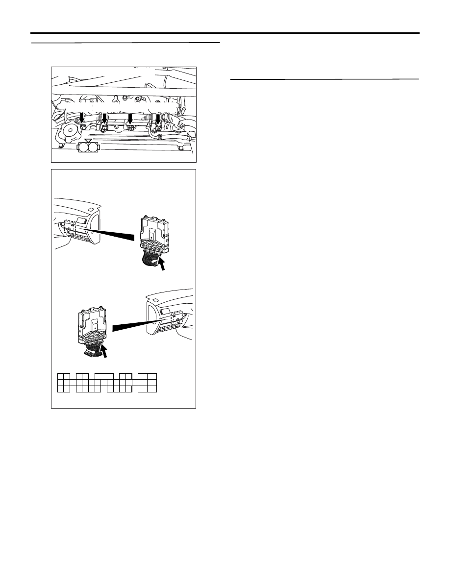
STEP 4. Connector check: Injector connector
a. B-22 (No. 1 injector connector)
b. B-20 (No. 2 injector connector)
c. B-18 (No. 3 injector connector)
d. B-17 (No. 4 injector connector)
Q: Are the check results normal?
YES :
Go to Step 5 .
NO :
Repair or replace the connector.
STEP 5. Check injector itself.
• Check Injector itself (Refer to
Q: Is the check result normal?
YES :
Go to Step 6 .
NO :
Replace the injector.
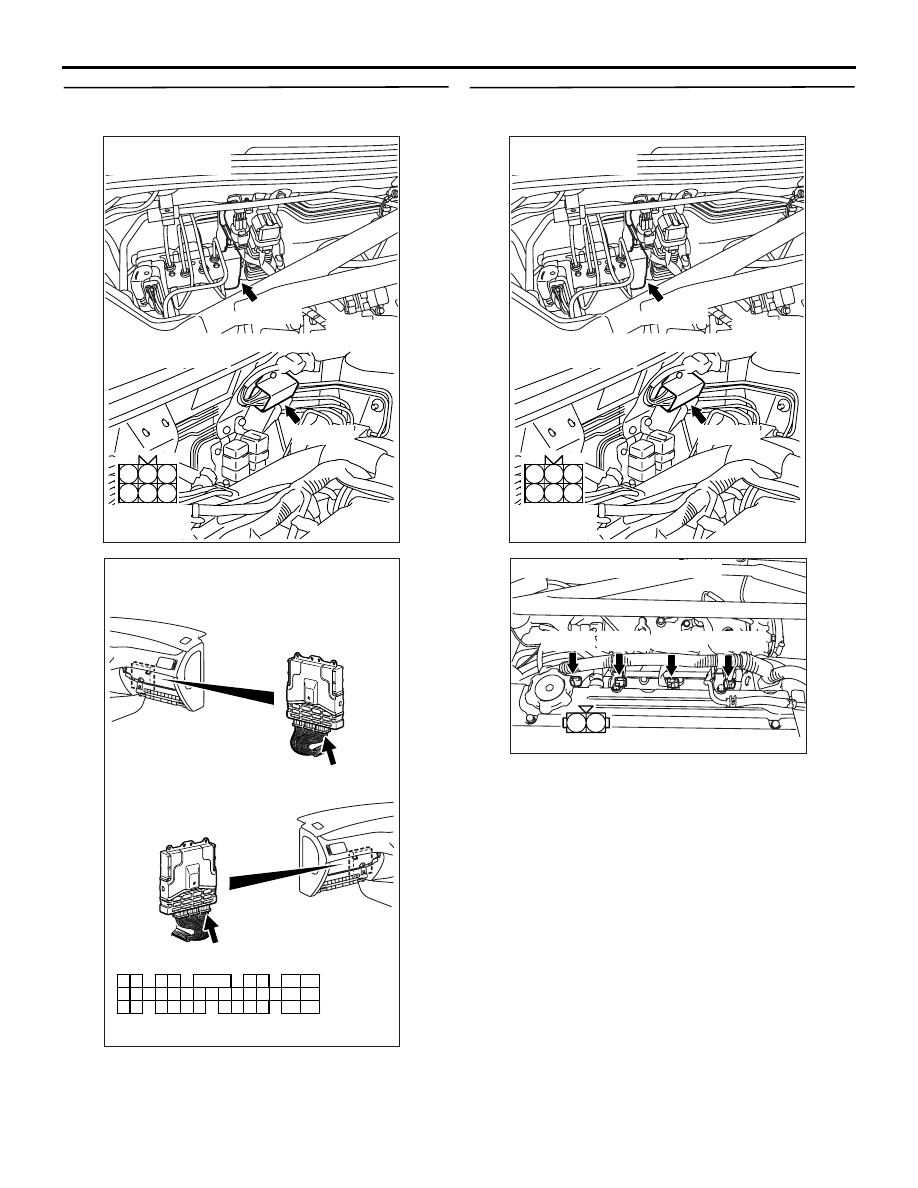
STEP 6. Connector check: C-121 engine-ECU
connector
Q: Is the check result normal?
YES :
Go to Step 7 .
NO :
Repair or replace the connector.
AK305012
1
2
Connector : B-17,B-18,B-20,B-22
Harness side connector
B-22(B) B-20(B) B-18(B) B-17(B)
AB
AK501995
2
3
4
5
6
7
8
9
11
12
13
14
15
16
17
18
19
20
30
21
22
23
24
25
26
27
28
29
31
32
33
34
35
1
10
AB
Connector: C-121
C-121 (GR)
C-121 (GR)
Harness side connector
<L. H. drive vehicles>
<R. H. drive vehicles>
TROUBLESHOOTING
MULTIPORT FUEL INJECTION (MPI)
13A-137
STEP 7. Check harness between injector
connector and C-121 engine-ECU connector.
a. Check harness between B-22 (terminal No. 2)
No. 1 injector connector and C-121 (terminal No.
1) engine-ECU connector.
b. Check harness between B-20 (terminal No. 2)
No. 2 injector connector and C-121 (terminal No.
9) engine-ECU connector.
c. Check harness between B-18 (terminal No. 2)
No. 3 injector connector and C-121 (terminal No.
24) engine-ECU connector.
d. Check harness between B-17 (terminal No. 2)
No. 4 injector connector and C-121 (terminal No.
2) engine-ECU connector.
• Check output line for damage.
Q: Are the check results normal?
YES :
Go to Step 8 .
NO :
Repair the damaged harness wire.
STEP 8. Check injector resistor itself.
• Check injector resistor itself (Refer to
).
Q: Is the check result normal?
YES :
Go to Step 9 .
NO :
Replace the injector resistor.
AK305012
1
2
Connector : B-17,B-18,B-20,B-22
Harness side connector
B-22(B) B-20(B) B-18(B) B-17(B)
AB
AK501995
2
3
4
5
6
7
8
9
11
12
13
14
15
16
17
18
19
20
30
21
22
23
24
25
26
27
28
29
31
32
33
34
35
1
10
AB
Connector: C-121
C-121 (GR)
C-121 (GR)
Harness side connector
<L. H. drive vehicles>
<R. H. drive vehicles>
TROUBLESHOOTING
MULTIPORT FUEL INJECTION (MPI)
13A-138
STEP 9. Connector check: B-119 injector resistor
connector and C-121 engine-ECU connector
Q: Is the check result normal?
YES :
Go to Step 10 .
NO :
Repair or replace the connector.
STEP 10. Check harness between B-119 injector
resistor connector and injector connector.
a. Check harness between B-119 (terminal No. 1)
injector resistor connector and B-22 (terminal No.
1) No. 1 injector connector.
b. Check harness between B-119 (terminal No. 4)
injector resistor connector and B-20 (terminal No.
1) No. 2 injector connector.
c. Check harness between B-119 (terminal No. 5)
injector resistor connector and B-18 (terminal No.
1) No. 3 injector connector.
d. Check harness between B-119 (terminal No. 6)
injector resistor connector and B-17 (terminal No.
1) No. 4 injector connector.
• Check output line for damage.
Q: Are the check results normal?
YES :
Go to Step 11 .
NO :
Repair the damaged harness wire.
AK305016
1
2
3
4
5
6
AB
Harness side
connector
B-119(B)
B-119(B)
Connector : B-119
<L.H.drive vehicles>
<R.H.drive vehicles>
AK501995
2
3
4
5
6
7
8
9
11
12
13
14
15
16
17
18
19
20
30
21
22
23
24
25
26
27
28
29
31
32
33
34
35
1
10
AB
Connector: C-121
C-121 (GR)
C-121 (GR)
Harness side connector
<L. H. drive vehicles>
<R. H. drive vehicles>
AK305016
1
2
3
4
5
6
AB
Harness side
connector
B-119(B)
B-119(B)
Connector : B-119
<L.H.drive vehicles>
<R.H.drive vehicles>
AK305012
1
2
Connector : B-17,B-18,B-20,B-22
Harness side connector
B-22(B) B-20(B) B-18(B) B-17(B)
AB
Нет комментариевНе стесняйтесь поделиться с нами вашим ценным мнением.
Текст