Mitsubishi Lancer Evolution IX. Manual — part 306

DRIVESHAFT ASSEMBLY
FRONT AXLE
26-17
• Check the boots for deterioration, damage or
cracking.
EBJ BOOT (RESIN BOOT)
REPLACEMENT
M1261005200435
AC102658
1. Remove the boot bands (large and small).
NOTE: The boot bands cannot be re-used.
2. Remove the EBJ boot.
3. Wrap a plastic tape around the shaft spline, and
assemble the boot band and EBJ boot.
AC102659
4. Align the centre groove on the EBJ boot small end
with the shaft groove.
AC102660
W
MB991561
Stopper
Adjusting bolt
AC
5. Turn the adjusting bolt on special tool boot band
crimping tool (MB991561) so that the size of the
opening (W) is at the standard value.
Standard value (W): 2.9 mm
<If it is larger than 2.9 mm> Tighten the adjust-
ing bolt.
<If it is smaller than 2.9 mm> Loosen the
adjusting bolt.
NOTE: The value of W will change by approxi-
mately 0.7 mm for each turn of the adjusting bolt.
NOTE: The adjusting bolt should not be turned
more than once.
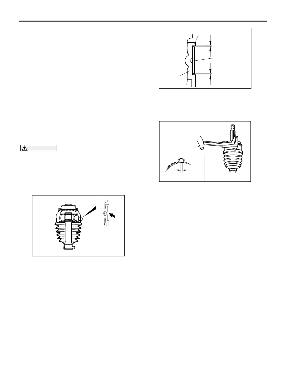
AC102661AC
Boot
A
Boot band
(small)
B
Projection
6. Position the EBJ boot band (small) so that there is
even clearance at either end (A and B).
CAUTION
• Secure the driveshaft in an upright position
and clamp part of the boot band to be crimped
securely in the jaws of special tool.
•
AC102663 AC
MB991561
Crimp the boot band until special tool
touches the stopper.
7. Use the special tool to crimp the boot band
(small).
AC102662
C
AD
8. Check that the crimping amount (C) of the boot
band is at the standard value.
Standard value (C): 2.4
− 2.8 mm
DRIVESHAFT ASSEMBLY
FRONT AXLE
26-18
<If the crimping amount is larger than
2.8 mm >
Readjust the value of (W) in step 5 according to
the following formula, and then repeat the
operation in step 7.
W = 5.5 mm
− C
Example: If C = 2.9 mm, then W = 2.6 mm.
<If the crimping amount is smaller than 2.4
mm >
Remove the EBJ boot band, readjust the value
of (W) in step 5 according to the following
formula, and then repeat the operations in
steps 6 and 7 using a new EBJ boot band.
W = 5.5 mm
− C
Example: If C = 2.3 mm, then W = 3.2 mm.
9. Check that the boot band is not sticking out past
the place where it has been installed. If the boot
band is sticking out, remove it and then repeat
steps 6 to 8, using a new boot band.
CAUTION
The driveshaft joint uses special grease. Do not
mix old and new or different types of grease.
10.Fill the inside of the boot with the specified
amount of the specified grease.
Specified grease: Repair kit grease
Amount to use: 100
± 10 g
AC102664 AC
11.Align the centre groove on the EBJ boot big end
with the EBJ case groove.
12.Follow the same procedure as in step 5 to adjust
the size of the opening (W) on the special tool so
that it is at the standard value.
Standard value (W): 3.2 mm
AC102665 AC
Boot
Projection
Boot band
(large)
D
E
13.Position the EBJ boot band (large) so that there is
even clearance at either end (D and E).
14.Use the special tool to crimp the EBJ boot band
(large) in the same way as in step 7.
AC102666
F
AD
15.Check that the crimping amount (F) of the boot
band is at the standard value.
Standard value (F): 2.4
− 2.8 mm
<If the crimping amount is larger than 2.8 mm
>
Readjust the value of (W) in step 12 according
to the following formula, and then repeat the
operation in step 14.
W = 5.8 mm
− F
Example: If F = 2.9 mm, then W = 2.9 mm.
<If the crimping amount is smaller than 2.4
mm >
Remove the EBJ boot band, readjust the value
of (W) in step 12 according to the following
formula, and then repeat the operations in
steps 13 and 14 using a new EBJ boot band.
W = 5.8 mm
− F
Example: If F = 2.3 mm, then W = 3.5 mm.
16.Check that the boot band is not sticking out past
the place where it has been installed. If the boot
band is sticking out, remove it and then repeat
steps 13 to 15, using a new boot band.
27-1
GROUP 27
CONTENTS
GENERAL INFORMATION . . . . . . . .
SERVICE SPECIFICATIONS. . . . . . .
LUBRICANTS . . . . . . . . . . . . . . . . . .
SEALANT. . . . . . . . . . . . . . . . . . . . . .
SPECIAL TOOLS. . . . . . . . . . . . . . . .
TROUBLESHOOTING . . . . . . . . . . . .
TROUBLESHOOTING STRATEGY . . . . . .
DIAGNOSIS FUNCTION. . . . . . . . . . . . . . .
DIAGNOSIS CODE CHART . . . . . . . . . . . .
DIAGNOSTIC TROUBLE CODE
PROCEDURES. . . . . . . . . . . . . . . . . . . . . .
SYMPTOM CHART. . . . . . . . . . . . . . . . . . .
INSPECTION PROCEDURE FOR TROUBLE
SYMPTOMS . . . . . . . . . . . . . . . . . . . . . . . .
DATA LIST REFERENCE TABLE . . . . . . .
ACTUATOR TEST REFERENCE TABLE. .
CHECK AT 4WD-ECU TERMINAL . . . . . . .
ON-VEHICLE SERVICE. . . . . . . . . . .
REAR AXLE TOTAL BACKLASH CHECK .
GEAR OIL LEVEL CHECK . . . . . . . . . . . . .
GEAR OIL REPLACEMENT . . . . . . . . . . . .
FLUID LEVEL CHECK . . . . . . . . . . . . . . . .
AYC BLEEDING . . . . . . . . . . . . . . . . . . . . .
AYC OPERATION CHECK . . . . . . . . . . . . .
OIL PRESSURE CHECK . . . . . . . . . . . . . .
WHEEL BEARING AXIAL PLAY CHECK . .
HUB BOLT REPLACEMENT. . . . . . . . . . . .
DIFFERENTIAL CARRIER OIL SEAL
REPLACEMENT . . . . . . . . . . . . . . . . . . . . .
REMEDY FOR A DISCHARGED BATTERY
REAR AXLE HUB ASSEMBLY . . . . .
REMOVAL AND INSTALLATION . . . . . . . .
INSPECTION. . . . . . . . . . . . . . . . . . . . . . . .
KNUCKLE . . . . . . . . . . . . . . . . . . . . . .
REMOVAL AND INSTALLATION . . . . . . . .
INSPECTION. . . . . . . . . . . . . . . . . . . . . . . .
DRIVESHAFT ASSEMBLY. . . . . . . . .
REMOVAL AND INSTALLATION . . . . . . . .
INSPECTION. . . . . . . . . . . . . . . . . . . . . . . .
DISASSEMBLY AND REASSEMBLY . . . . .
DIFFERENTIAL CARRIER
ASSEMBLY. . . . . . . . . . . . . . . . . . . . .
REMOVAL AND INSTALLATION . . . . . . . .
DIFFERENTIAL SUPPORT MEMBER
BUSHING REPLACEMENT . . . . . . . . . . . .
DISASSEMBLY AND REASSEMBLY . . . . .
REMOVAL AND INSTALLATION . . . . . . . .
HYDRAULIC UNIT DISPOSAL . . . . . . . . . .

GENERAL INFORMATION
REAR AXLE
27-2
GENERAL INFORMATION
M1271000100382
The rear axle consists of rear wheel hub assembly,
knuckles and driveshafts, and has the following fea-
tures:
• The wheel bearing is a unit ball bearing (dou-
ble-row angular contact ball bearing) for reduced
friction.
• The driveshaft has EBJ-TJ constant velocity
joints.
• ABS rotor for detecting the wheel speed is
press-fitted to the EBJ.
• For environmental protection, lead-free grease is
used on the joints.
Active Yaw Control (AYC) is adopted to improve the
turning performance. AYC incorporates the torque
transfer differential and the hydraulic unit.
EBJ:Eight Ball Fixed Joint; The use of the
smaller-sized eight balls inside the joint achieves
weight saving and compact size compared with a
BJ (Birfield Joint).
TJ: Tripod Joint
SPECIFICATIONS
Item
Specification
Wheel bearing
Type
Unit ball bearing (Double-row angular
contact ball bearing)
Bearing (OD x ID) mm
70
× 40
Driveshaft
Type
Outer
EBJ
Inner
TJ
Length (joint to joint)
×
diameter mm
Left
428.5
× 25
Right
448.5
× 25
CONSTRUCTION DIAGRAM
AC310259
Rear hub
BJ
TJ
Driveshaft
Differential carrier
AB
ABS rotor
Нет комментариевНе стесняйтесь поделиться с нами вашим ценным мнением.
Текст