Mitsubishi Lancer Evolution IX. Manual — part 426

TROUBLESHOOTING
MULTIPORT FUEL INJECTION (MPI)
13A-179
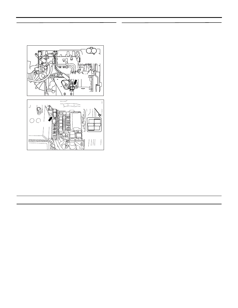
STEP 8. Connector check: C-121 engine-ECU
connector
Q: Is the check result normal?
YES :
Go to Step 9 .
NO :
Repair or replace the connector.
STEP 9. Check harness between B-101 (terminal
No. 2) EGR control solenoid valve connector and
C-121 (terminal No. 6) engine-ECU connector.
NOTE: Before checking harness, check intermediate
connector B-14, and repair if necessary.
• Check output line for damage.
Q: Is the check result normal?
YES :
Go to Step 10 .
NO :
Repair the damaged harness wire.
AK501995
2
3
4
5
6
7
8
9
11
12
13
14
15
16
17
18
19
20
30
21
22
23
24
25
26
27
28
29
31
32
33
34
35
1
10
AB
Connector: C-121
C-121 (GR)
C-121 (GR)
Harness side connector
<L. H. drive vehicles>
<R. H. drive vehicles>
AK305024
1
2
AB
Connector : B-101
Harness side
connector
B-101(BR)
AK501995
2
3
4
5
6
7
8
9
11
12
13
14
15
16
17
18
19
20
30
21
22
23
24
25
26
27
28
29
31
32
33
34
35
1
10
AB
Connector: C-121
C-121 (GR)
C-121 (GR)
Harness side connector
<L. H. drive vehicles>
<R. H. drive vehicles>
TROUBLESHOOTING
MULTIPORT FUEL INJECTION (MPI)
13A-180
STEP 10. Check harness between B-101 (terminal
No. 1) EGR control solenoid valve connector and
B-12X (terminal No. 4) engine control relay
connector.
NOTE: Before checking harness, check intermediate
connector B-14, and repair if necessary.
• Check power supply line for damage.
Q: Is the check result normal?
YES :
Go to Step 11 .
NO :
Repair the damaged harness wire.
STEP 11. M.U.T.-II /III actuator test
• Item No. 10: EGR control solenoid valve
OK: Operating sound can be heard and the
valve vibrates.
Q: Is the check result normal?
YES :
Intermittent malfunction (Refer to GROUP
00
− How to Use
Troubleshooting/Inspection Service Points
).
NO :
Replace the engine-ECU.
Code No. P0421: Warm up Catalyst Malfunction
FUNCTION
• The signal from the oxygen sensor (rear) differs
from the oxygen sensor (front). That is because
the catalytic converter purifies exhaust gas.
When the catalytic converter has deteriorated,
the signal from the oxygen sensor (front)
becomes similar to the oxygen sensor (rear).
• The engine-ECU compares the output of the front
and rear oxygen sensor signals.
TROUBLE JUDGMENT
Check Conditions
• The engine speed is 3,000 r/min. or less.
• The accelerator pedal is fully depressed.
• Airflow sensor output is 8 gm/s or higher.
• 3 seconds or longer has elapsed after the
above-mentioned conditions have been met.
• Engine running, intake air temperature is −10°C
or higher.
• Under the closed-loop control.
• Vehicle speed is 1.5 km/h or more.
• The engine-ECU monitors for this condition for 7
cycles of 10 seconds each during the drive cycle.
• Short-term fuel trim is higher than −25% or lower
than +25%.
• Accumulated air flow sensor output is 2,931 g or
higher.
Judgment Criterion
• The oxygen sensor (rear) signal frequency
divided by oxygen sensor (front) signal frequency
= 0.8 or more.
AK305024
1
2
AB
Connector : B-101
Harness side
connector
B-101(BR)
AK305003
2
1
3
4
AB
Connector : B-12X
B-12X
Harness side
connector
Relay box’s
triangle marks

TROUBLESHOOTING
MULTIPORT FUEL INJECTION (MPI)
13A-181
PROBABLE CAUSES
• Catalytic converter deteriorated
• Failed oxygen sensor (front)
• Failed oxygen sensor (rear)
• Failed engine-ECU
DIAGNOSIS PROCEDURE
STEP 1. Check for leakage of exhaust emission
from exhaust manifold.
Q: Is the check result normal?
YES :
Go to Step 2 .
NO :
Repair.
STEP 2. M.U.T.-II/III data list
• Refer to Data List Reference Table
.
a. Item No. 11: Oxygen sensor (front)
b. Item No. 59: Oxygen sensor (rear)
Q: Is the check result normal?
YES :
Go to Step 3 .
NO :
Perform the diagnosis code classified check
procedure for the sensor that has shown an
abnormal data valve (Refer to Inspection
Chart for Diagnosis Codes
).
STEP 3. M.U.T.-II/III data list
• Item No. 11: Oxygen sensor (front)
OK: 0
− 0.4 and 0.6 − 1.0 volt should alternate
15 times or more within 10 seconds (engine
speed at 2,000 r/min.).
Q: Is the check result normal?
YES :
Go to Step 4 .
NO :
Replace the oxygen sensor (front).
STEP 4. Replace the oxygen sensor (rear).
• After replacing the oxygen sensor (rear),
re-check the trouble symptoms.
Q: Is the check result normal?
YES :
The check is end.
NO :
Go to Step 5 .
STEP 5. Replace the catalytic converter.
• After replacing the catalytic converter, re-check
the trouble symptoms.
Q: Is the check result normal?
YES :
The check is end.
NO :
Replace the engine-ECU.

TROUBLESHOOTING
MULTIPORT FUEL INJECTION (MPI)
13A-182
Code No. P0443: Purge Control Solenoid Valve System
OPERATION
• Power is supplied to the purge control solenoid
valve (terminal No. 2) from the engine control
relay (terminal No. 4).
• The engine-ECU (terminal No. 16) makes the
power transistor in the unit be in "ON" position,
and that makes currents go on the purge control
solenoid valve (terminal No. 1).
1
2
3
4
2
1
AK501815
2
3 4
5 6
7 8
9
11 12 13 14 15 16 17 18 19 20
30
21 22 23
24 25
26 27 28 29
3132 33
34 35
1
10
Engine control relay
B-12X
16
Engine-ECU
B-02
MU802779
Purge control solenoid valve
1
2
Purge control solenoid valve circuit
R-Y
Y-G
Wire colour code
B: Black LG: Light green G: Green L: Blue W: White Y: Yellow SB: Sky blue BR: Brown O: Orange GR: Gray
R: Red P: Pink V: Violet PU: Purple
C-121
(MU803784)
AB
Battery
B-Y
6 <A-13> (*1) or
13 <C-31> (*2)
B-Y
B-Y
NOTE
*1: L.H. drive vehicles
*2: R.H. drive vehicles
2
1
4
3
To engine-ECU
Нет комментариевНе стесняйтесь поделиться с нами вашим ценным мнением.
Текст