Mitsubishi Lancer Evolution IX. Manual — part 179

INPUT SIGNAL PROCEDURES
SMART WIRING SYSTEM (SWS) NOT USING SWS MONITOR
54B-279
COMMENTS ON TROUBLE SYMPTOM
Vehicle speed sensor signal is used to operate the
windshield wiper (vehicle speed-dependent wiper
function). If this signal is abnormal, the windshield
wipers do not work normally.
POSSIBLE CAUSES
• Malfunction of the vehicles speed sensor
• Malfunction of the ETACS-ECU
• Damaged harness wires and connectors
DIAGNOSTIC PROCEDURE
Step 1. Check the speedometer.
Check that the speedometer works normally.
Q: Is the check result normal?
YES :
Go to Step 2.
NO :
Diagnose the combination meter (Refer to
GROUP 54A
− Combination meter
).
Vehicle Speed Signal Input Circuit <RHD>
Wire colour code
B : Black LG : Light green G : Green L : Blue W : White Y : Yellow SB : Sky blue
BR : Brown O : Orange GR : Grey R : Red P : Pink V : Violet PU : Purple
ETACS-ECU
VEHICLE
SPEED SENSOR

INPUT SIGNAL PROCEDURES
SMART WIRING SYSTEM (SWS) NOT USING SWS MONITOR
54B-280
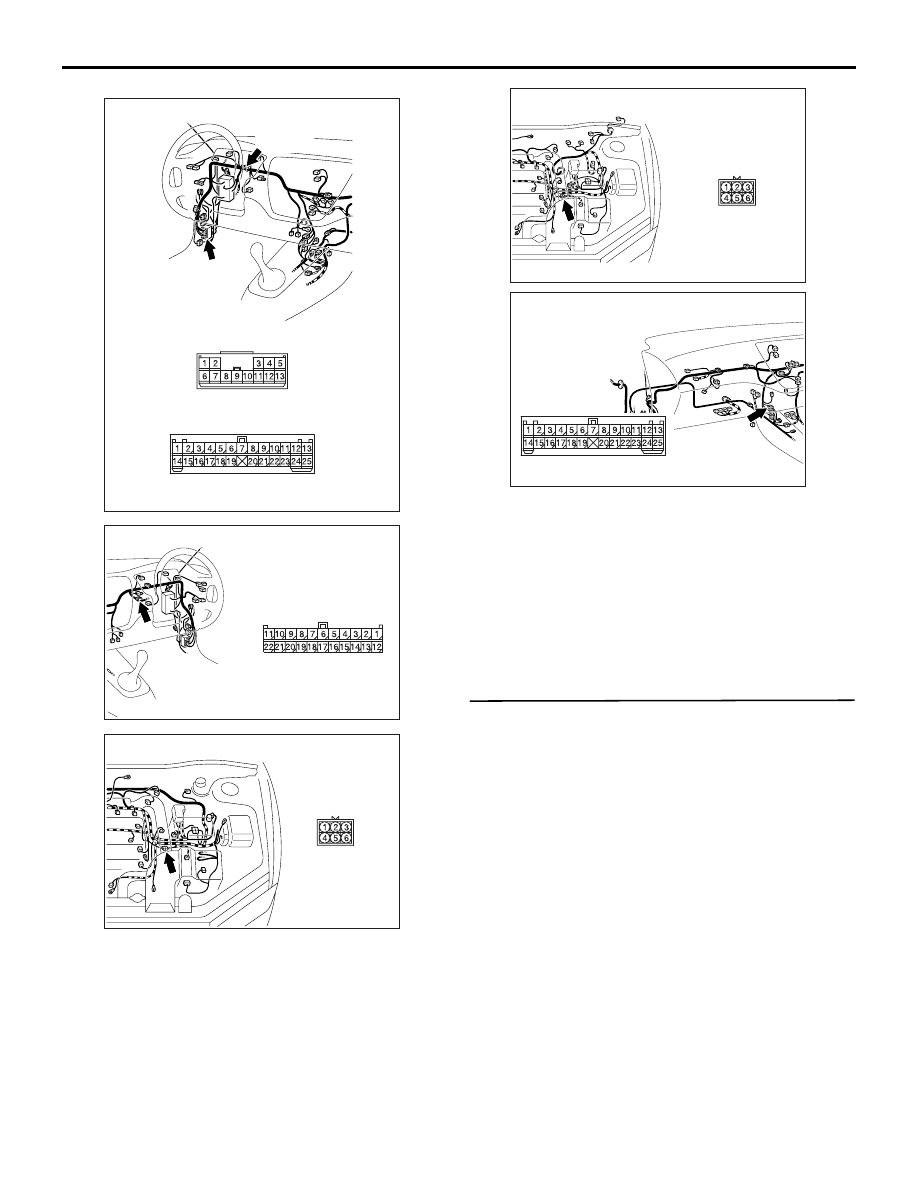
Step 2. Connector check: B-04 vehicles speed
sensor connector and C-228 ETACS-ECU
connector
Q: Are the check result normal?
YES :
Go to Step 3.
NO :
Repair the defective connector.
Step 3. Check the wiring harness between B-04
vehicles speed sensor connector terminal No.3
and C-228 ETACS-ECU connector terminal No.63.
AC310450
Connector: C-228
AH
Junction block
(rear view)
Harness side
<LHD>
51
52
53
54
55
56
57
58
59
58 5756 55 54 53 52 51 60
74 7372
71 70 69
AC310461
Harness side
Junction block (rear view)
Connector: C-228
AG
<RHD>
51
52
53
54
55
56
57
58
59
58 5756 55 54 53 52 51 60
74 7372
71 70 69
AC310439AB
B-04(B)
Harness side
Connector: B-04
<LHD>
AC310477
Connector: B-04
<RHD>
AB
Harness side
B-04(B)
INPUT SIGNAL PROCEDURES
SMART WIRING SYSTEM (SWS) NOT USING SWS MONITOR
54B-281
NOTE:
Prior to the wiring harness inspection, check joint
connector C-21 <LH driver vehicles>, combination
meter connector C-101 <RH drive vehicles> and
intermediate connector B-27 and C-124, and repair if
necessary.
• Check the input line for open circuit.
Q: Is the check result normal?
YES :
Go to Step 4.
NO :
Repair the wiring harness.
Step 4. Retest the system.
Check that the vehicle speed sensor signal is
received normally.
Q: Is the check result normal?
YES :
The trouble can be an intermittent
malfunction (Refer to GROUP 00
− How to
Cope with Intermittent Malfunction
NO :
Replace the ETACS-ECU.
AC310447
Connector: C-21,C-124
<LHD>
AD
C-21 (B)
C-124 (B)
C-124
C-21
AC310456
Connector: C-101
<RHD>
AF
Harness side
AC310439
Connector: B-27 <LHD>
AC
AC310477
Connector: B-27 <RHD>
AC
AC310454
Connector: C-124
<RHD>
AD
INPUT SIGNAL PROCEDURES
SMART WIRING SYSTEM (SWS) NOT USING SWS MONITOR
54B-282
INSPECTION PROCEDURE L-13: Each switch signal of the keyless entry transmitter is not received.
CAUTION
Whenever the ECU is replaced, ensure that the
input signal circuit is normal.
COMMENTS ON TROUBLE SYMPTOM
Input signal from the keyless entry transmitter is
used to operate the keyless entry system. If the sig-
nal is abnormal, the keyless entry system will not
work normally.
POSSIBLE CAUSES
• Malfunction of the keyless entry transmitter
• Defective battery of the keyless entry transmitter
• Malfunction of the ETACS-ECU
DIAGNOSTIC PROCEDURE
Step 1. Pulse check
Check whether the ETACS-ECU receives signal from
a transmitter or not. For this check, you should use
the 2-button-type transmitter (integrated with a key),
which cover screw is silver and has already been
registered.
NOTE: For how to register the keyless entry trans-
mitter encrypted code, refer to GROUP 42
−
On-vehicle Service
.
OK: The M.U.T.-II/III sounds or the voltmeter
needle fluctuates.
Q: Is the check result normal?
YES :
Go to Step 2.
NO :
Go to Step 4.
Step 2. Check the transmitter battery.
Refer to GROUP 42
− Keyless entry system
.
Q: Is the check result normal?
YES :
Go to Step 3.
NO :
Replace the keyless entry transmitter
battery.
Step 3. Register the encrypted code, and then
retest the system.
(1) Register the keyless entry transmitter again.
(2) Check that each signal is received from the
keyless entry transmitter.
Q: Is the check result normal?
YES :
The trouble can be an intermittent
malfunction (Refer to GROUP 00
− How to
Cope with Intermittent Malfunction
NO :
Replace the keyless entry transmitter.
Step 4. Retest the system.
Check that each signal is received from the keyless
entry transmitter.
Q: Is the check result normal?
YES :
The trouble can be an intermittent
malfunction (Refer to GROUP 00
− How to
Cope with Intermittent Malfunction
NO :
Replace the ETACS-ECU.
W3Z10E39AA
KEYLESS ENTRY
TRANSMITTER
KEYLESS ENTRY
RECEIVER
ETACS-ECU
Transmitter Input Circuit
System switch
Check condition
Keyless entry transmitter
"LOCK/UNLOCK" switch
When the switch is
turned from off to on
Нет комментариевНе стесняйтесь поделиться с нами вашим ценным мнением.
Текст