Mitsubishi Lancer Evolution IX. Manual — part 396

TROUBLESHOOTING
MULTIPORT FUEL INJECTION (MPI)
13A-59
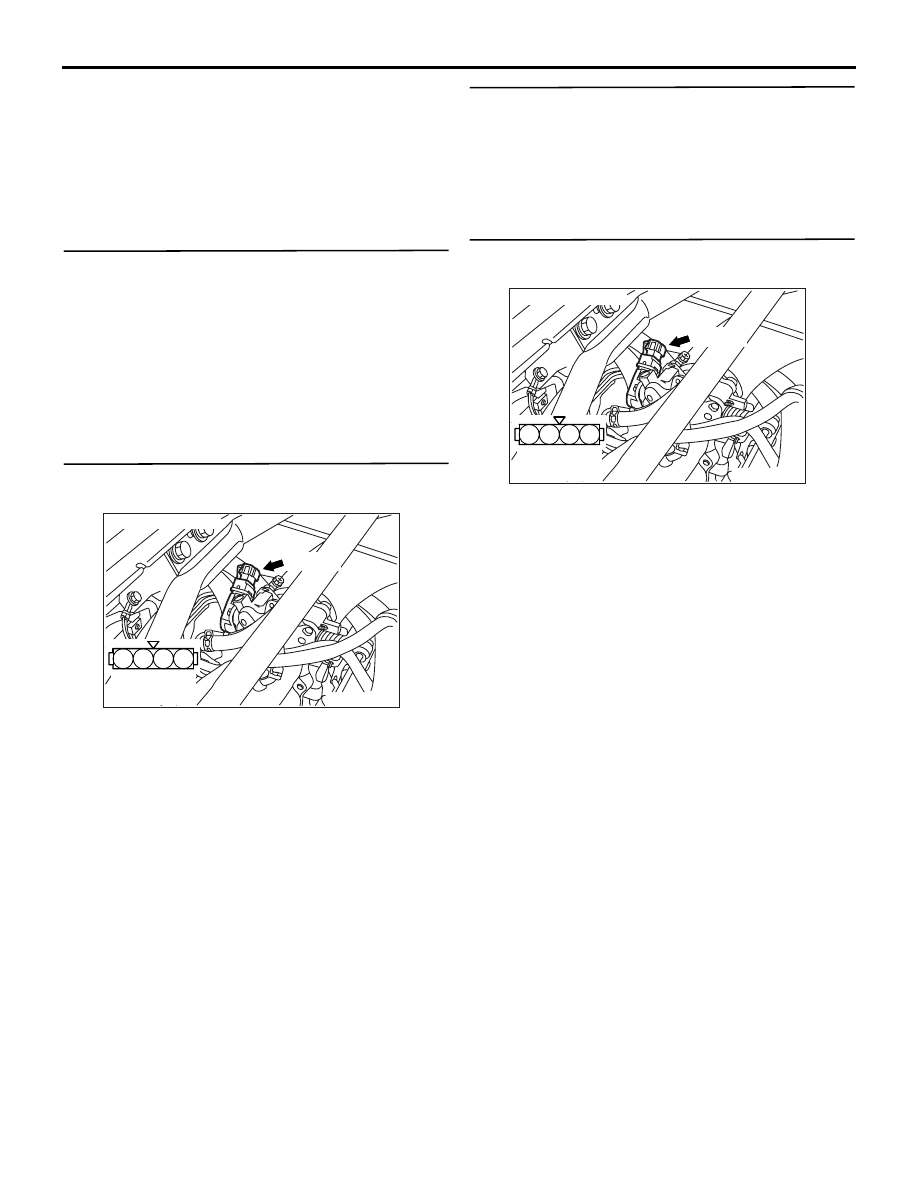
STEP 15. Check harness between B-107 (terminal
No. 1) engine coolant temperature sensor
connector and C-119 (terminal No. 44)
engine-ECU connector.
• Check output line for damage.
Q: Is the check result normal?
YES :
Go to Step 16 .
NO :
Repair the damaged harness wire.
STEP 16. Connector check: C-119 engine-ECU
connector
Q: Is the check result normal?
YES :
Check harness between B-107 (terminal
No. 2) engine coolant temperature sensor
connector and C-119 (terminal No. 49)
engine-ECU connector.
• Check earthing line for damage.
NO :
Repair or replace the connector.
AK305008
1
2
AB
Connector : B-107
Harness side
connector
B-107(B)
AK501994
65
43
50
42
49
41
48
60
61
64
46
47
58
59
67
68
45
56
66
52 51
44
53
62
54
63
57
55
AB
Connector: C-119
C-119 (GR)
C-119 (GR)
Harness side connector
<L. H. drive vehicles>
<R. H. drive vehicles>
AK501994
65
43
50
42
49
41
48
60
61
64
46
47
58
59
67
68
45
56
66
52 51
44
53
62
54
63
57
55
AB
Connector: C-119
C-119 (GR)
C-119 (GR)
Harness side connector
<L. H. drive vehicles>
<R. H. drive vehicles>
AK305008
1
2
AB
Connector : B-107
Harness side
connector
B-107(B)

TROUBLESHOOTING
MULTIPORT FUEL INJECTION (MPI)
13A-60
Code No. P0120: Throttle Position Sensor System
OPERATION
• The power voltage of 5 V is applied to the throttle
position sensor (terminal No. 1) from the
engine-ECU (terminal No. 42).
• The power voltage is earthed to the engine-ECU
(terminal No. 49) from the throttle position sensor
(terminal No. 4).
• The sensor signal is inputted to the engine-ECU
(terminal No. 78) from the throttle position sensor
output terminal (terminal No. 2).
FUNCTION
• The throttle position sensor converts the opening
of the throttle valve into a voltage and inputs the
voltage signal to the engine-ECU.
• In response to the signal, the engine-ECU checks
the opening of the throttle valve.
TROUBLE JUDGMENT
Check Condition
• Ignition switch: "ON" (Exclude 2 seconds after the
ignition switch has been in "ON" position or just
after the engine has started up.)
Judgment Criterion
• The sensor output voltage is 0.2 V or less for 2
seconds.
Check Conditions
• Engine speed of 1,000 r/min. or less.
• Volumetric efficiency 60% or less.
Judgment Criterion
• The sensor output voltage is 2.0 V or more for 2
seconds.
2 3 4
1
AK501804
65
43
50
42
49
41
48
60 61
64
46 47
58 59
67 68
45
56
66
52
51
44
53
62
54
63
57
55
80
87
81
94
85
82
84
93
86
98
99
74
92
73
83
88
91
95
97
96
100
89
78
71
90
76 77
75
72
79
5 V
Engine-ECU
49
78
42
B-03
(MU802724)
Throttle position sensor
1
2
4
Throttle position sensor circuit
Wire colour code
B: Black LG: Light green G: Green L: Blue W: White Y: Yellow SB: Sky blue BR: Brown O: Orange GR: Gray
R: Red P: Pink V: Violet PU: Purple
AB
B
G
GR
C-119
(MU803782)
C-117
(MU803783)
TROUBLESHOOTING
MULTIPORT FUEL INJECTION (MPI)
13A-61
PROBABLE CAUSES
• Failed throttle position sensor
• Open/short circuit in throttle position sensor cir-
cuit or loose connector contact
• Failed engine-ECU
DIAGNOSIS PROCEDURE
STEP 1. M.U.T.-II/III data list
• Refer to Data List Reference Table
.
a. Item No. 14: Throttle position sensor
Q: Is the check result normal?
YES :
Intermittent malfunction (Refer to GROUP
00
− How to Use
Troubleshooting/Inspection Service Points
).
NO :
Go to Step 2 .
STEP 2. Connector check: B-03 throttle position
sensor connector
Q: Is the check result normal?
YES :
Go to Step 3 .
NO :
Repair or replace the connector.
STEP 3. Check throttle position sensor itself.
• Check throttle position sensor itself (Refer to
).
Q: Is the check result normal?
YES :
Go to Step 4 .
NO :
Replace the throttle position sensor.
STEP 4. Perform voltage measurement at B-03
throttle position sensor connector.
• Disconnect connector, and measure at harness
side.
• Ignition switch: "ON"
• Voltage between terminal No. 1 and earth.
OK: 4.9
− 5.1 V
Q: Is the check result normal?
YES :
Go to Step 10 .
NO :
Go to Step 5 .
AK305010
2 1
3
4
AB
Connector : B-03
Harness side
connector
B-03(B)
AK305010
2 1
3
4
AB
Connector : B-03
Harness side
connector
B-03(B)

TROUBLESHOOTING
MULTIPORT FUEL INJECTION (MPI)
13A-62
STEP 5. Perform voltage measurement at C-119
engine-ECU connector.
• Measure engine-ECU terminal voltage.
• Ignition switch: "ON"
• Voltage between terminal No. 42 and earth.
OK: 4.9
− 5.1 V
Q: Is the check result normal?
YES :
Go to Step 6 .
NO :
Go to Step 7 .
STEP 6. Connector check: C-119 engine-ECU
connector
Q: Is the check result normal?
YES :
Check and repair harness between B-03
(terminal No. 1) throttle position sensor
connector and C-119 (terminal No. 42)
engine-ECU connector.
• Check power supply line for open
circuit.
NO :
Repair or replace the connector.
AK501994
65
43
50
42
49
41
48
60
61
64
46
47
58
59
67
68
45
56
66
52 51
44
53
62
54
63
57
55
AB
Connector: C-119
C-119 (GR)
C-119 (GR)
Harness side connector
<L. H. drive vehicles>
<R. H. drive vehicles>
AK501994
65
43
50
42
49
41
48
60
61
64
46
47
58
59
67
68
45
56
66
52 51
44
53
62
54
63
57
55
AB
Connector: C-119
C-119 (GR)
C-119 (GR)
Harness side connector
<L. H. drive vehicles>
<R. H. drive vehicles>
AK305010
2 1
3
4
AB
Connector : B-03
Harness side
connector
B-03(B)
Нет комментариевНе стесняйтесь поделиться с нами вашим ценным мнением.
Текст