Mitsubishi Lancer Evolution IX. Manual — part 602

TROUBLESHOOTING <ACD>
MANUAL TRANSMISSION (FF)
22A-91
Check for the contact with terminals.
Q: Is the check result normal?
YES :
Go to Step 5.
NO :
Repair the defective connector.
STEP 5. Check the harness between ACD mode
changeover switch connector C-135 terminal
No.2 and ignition switch.
Check the power supply line for short or open circuit.
Q: Is the check result normal?
YES :
Go to Step 6.
NO :
Repair the wiring harness.
STEP 6. M.U.T.-II/III data list
Item 63: ACD mode changeover switch (Refer to
data list reference table
).
Q: Is the check result normal?
YES :
Intermittent malfunction (Refer to GROUP
00
− How to Cope with Intermittent
).
NO :
Replace the 4WD-ECU.
STEP 7. Measure the voltage at 4WD-ECU
connector C-26.
(1) Turn the ignition switch to the ON position.
(2) Measure the voltage between 4WD-ECU
connector C-26 terminal No.47 and earth.
OK: System voltage
Q: Is the check result normal?
YES :
Go to Step 10.
NO :
Go to Step 8.
AC310458
AT
Connector: C-210,
C-211 <RH drive vehicles>
Junction block (front view)
C-210
C-210
C-211
C-211
AC311015AI
Connector: C-135 <LH drive vehicles>
C-135
AC311037
C-135
AD
Connector: C-135 <RH drive vehicles>
AC311002
4WD-ECU
Harness side
C-26 (Y)
AC
Connector: C-26
4WD-ECU
C-26 (Y)
Rear console
assembly
<LH drive vehicles>
<RH drive vehicles>

TROUBLESHOOTING <ACD>
MANUAL TRANSMISSION (FF)
22A-92
STEP 8. Connectors check: C-26 4WD-ECU
connector, C-122 intermediate connector, C-135
ACD mode changeover switch connector <LH
drive vehicles> or C-26 4WD-ECU connector,
C-138 intermediate connector, C-135 ACD mode
changeover switch connector <RH drive
vehicles>.
Check for the contact with terminals.
Q: Is the check result normal?
YES :
Go to Step 9.
NO :
Repair the defective connector.
AC311002
4WD-ECU
Harness side
C-26 (Y)
AC
Connector: C-26
4WD-ECU
C-26 (Y)
Rear console
assembly
<LH drive vehicles>
<RH drive vehicles>
AC311015AC
Connector: C-122 <LH drive vehicles>
C-122
AC311016AB
Connector: C-138 <RH drive vehicles>
C-138
AC311015AI
Connector: C-135 <LH drive vehicles>
C-135
AC311037
C-135
AD
Connector: C-135 <RH drive vehicles>

TROUBLESHOOTING <ACD>
MANUAL TRANSMISSION (FF)
22A-93
STEP 9. Check the harness between 4WD-ECU
connector C-26 terminal No.47 and ACD mode
changeover switch connector C-135 terminal
No.1.
Check the output line for short or open circuit.
Q: Is the check result normal?
YES :
Go to Step 6.
NO :
Repair the wiring harness.
STEP 10. Connector check: C-26 4WD-ECU
connector.
Check for the contact with terminals.
Q: Is the check result normal?
YES :
Go to Step 6.
NO :
Repair the defective connector.
AC311002
4WD-ECU
Harness side
C-26 (Y)
AC
Connector: C-26
4WD-ECU
C-26 (Y)
Rear console
assembly
<LH drive vehicles>
<RH drive vehicles>
AC311015AI
Connector: C-135 <LH drive vehicles>
C-135
AC311037
C-135
AD
Connector: C-135 <RH drive vehicles>
AC311002
4WD-ECU
Harness side
C-26 (Y)
AC
Connector: C-26
4WD-ECU
C-26 (Y)
Rear console
assembly
<LH drive vehicles>
<RH drive vehicles>
TROUBLESHOOTING <ACD>
MANUAL TRANSMISSION (FF)
22A-94
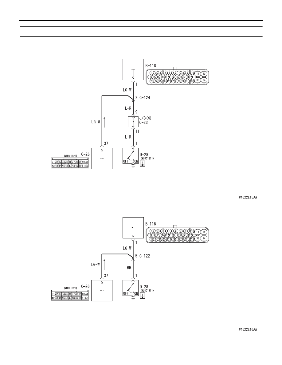
Code No.63 Parking brake switch system
Parking brake switch system circuit <LH drive vehicles>
4WD-ECU
PARKING BRAKE SWITCH
ABS-ECU
Wire colour code
B : Black LG : Light green G : Green L : Blue W : White Y : Yellow SB : Sky blue
BR : Brown O : Orange GR : Gray R : Red P : Pink V : Violet
Parking brake switch system circuit <RH drive vehicles>
4WD-ECU
PARKING BRAKE SWITCH
ABS-ECU
Wire colour code
B : Black LG : Light green G : Green L : Blue W : White Y : Yellow SB : Sky blue
BR : Brown O : Orange GR : Gray R : Red P : Pink V : Violet
Нет комментариевНе стесняйтесь поделиться с нами вашим ценным мнением.
Текст