Mitsubishi Lancer Evolution IX. Manual — part 154

SYMPTOM PROCEDURES
SMART WIRING SYSTEM (SWS) NOT USING SWS MONITOR
54B-179
NOTE:
Prior to the wiring harness inspection, check interme-
diate connector F-12 <licence plate lamp> and repair
if necessary.
• Check the earth wires for open circuit.
Q: Is the check result normal?
YES :
The trouble can be an intermittent
malfunction (Refer to GROUP 00
− How to
Cope with Intermittent Malfunction
NO :
Repair the wiring harness.
Step 5. Connector check: A-10X front-ECU
connector
Q: Is the check result normal?
YES :
Go to Step 6.
NO :
Repair the defective connector.
AC310469
AG
Connector: F-12 <RHD>
F-12 (GR)
AC310572AB
Connector: A-10X
Relay box side
10
11
5
9 8 7 6
4 3
1
2
Battery

SYMPTOM PROCEDURES
SMART WIRING SYSTEM (SWS) NOT USING SWS MONITOR
54B-180
Step 6. Check the wiring harness from F-14 <tail
lamp LH> or F-08 <tail lamp RH> rear
combination lamp connector terminal No.3, A-31
<position lamp LH> or A-39 <position lamp RH>
headlamp assembly connector terminal No.3,
F-11 <licence plate lamp LH> or F-10 <licence
plate lamp RH> licence plate lamp connector
terminal No.2, C-02 <tail lamp indicator>
combination meter connector terminal No.38 to
A-10X front-ECU connector terminal No.8.
AC310470
Connectors: F-08, F-10, F-11, F-14
<RHD>
AD
F-08(B)
F-10(GR)
F-11(GR)
F-14(B)
Harness side
F-08
Harness side
F-11
Harness side
F-10
Harness side
F-14
AC310475
Connectors: A-31
AB
A-31(B)
Harness side
A-31
<RHD>
AC310433
Connectors: A-39
AD
A-39(B)
Harness side
A-39
<RHD>
AC310456
Connector: C-02
<RHD>
AK
Harness side
31
35
36
37
38
39
40
41
45
46
47
48
49
50
51
34
44
33
43
32
42
C-02 (L)
AC310572AB
Connector: A-10X
Relay box side
10
11
5
9 8 7 6
4 3
1
2
Battery
AC310572AB
Connector: A-10X
Relay box side
10
11
5
9 8 7 6
4 3
1
2
Battery

SYMPTOM PROCEDURES
SMART WIRING SYSTEM (SWS) NOT USING SWS MONITOR
54B-181
NOTE:
Prior to the wiring harness inspection, check interme-
diate connector C-129 <tail lamp, licence plate lamp
or tail lamp indicator>, C-127 <tail lamp LH or licence
plate lamp> or F-12 <licence plate lamp>, joint con-
nector C-05 <tail lamp RH, or tail lamp indicator>,
junction block connector C-210 <tail lamp RH, or tail
lamp indicator>, C-214 <tail lamp indicator> or C-217
<tail lamp RH> and repair if necessary.
• Check the output lines for open circuit.
Q: Is the check result normal?
YES :
Go to Step 7.
NO :
Repair the wiring harness.
Step 7. Retest the system.
Check that the tail lamps, the position lamps and the
licence plate lamps illuminate normally.
Q: Is the check result normal?
The all lamps illuminate normally :
The trouble can
be an intermittent malfunction (Refer to
GROUP 00
− How to Cope with Intermittent
).
When the tail lamps do not illuminate :
Replace
the rear combination lamp socket assembly.
When the position lamps do not illuminate :
Replace the position lamp socket.
When the licence plate lamps do not illuminate :
Replace the licence plate lamp socket.
When the tail lamp indicator do not illuminate :
Replace the combination meter assembly.
AC310455
C-127
C-129
Connectors: C-127, C-129
AE
C-129
<RHD>
C-127
AC310469
AG
Connector: F-12 <RHD>
F-12 (GR)
AC310454
Connectors: C-05
AZ
<RHD>
C-05
C-05
AC310459
C-214
Harness side
21
7
16 15
17
18
20 19
1
2
3
4
5
6
23 22
24
25
28
26
27
9
8
10
11
14
12
13
Connectors: C-210, C-214, C-217
AE
C-214
Junction block (front view)
<RHD>
C-210
C-210
Harness side
10
1
6
14
5
12
13
4
11
7
2
3
8
9
C-217
C-217
Harness side
SYMPTOM PROCEDURES
SMART WIRING SYSTEM (SWS) NOT USING SWS MONITOR
54B-182
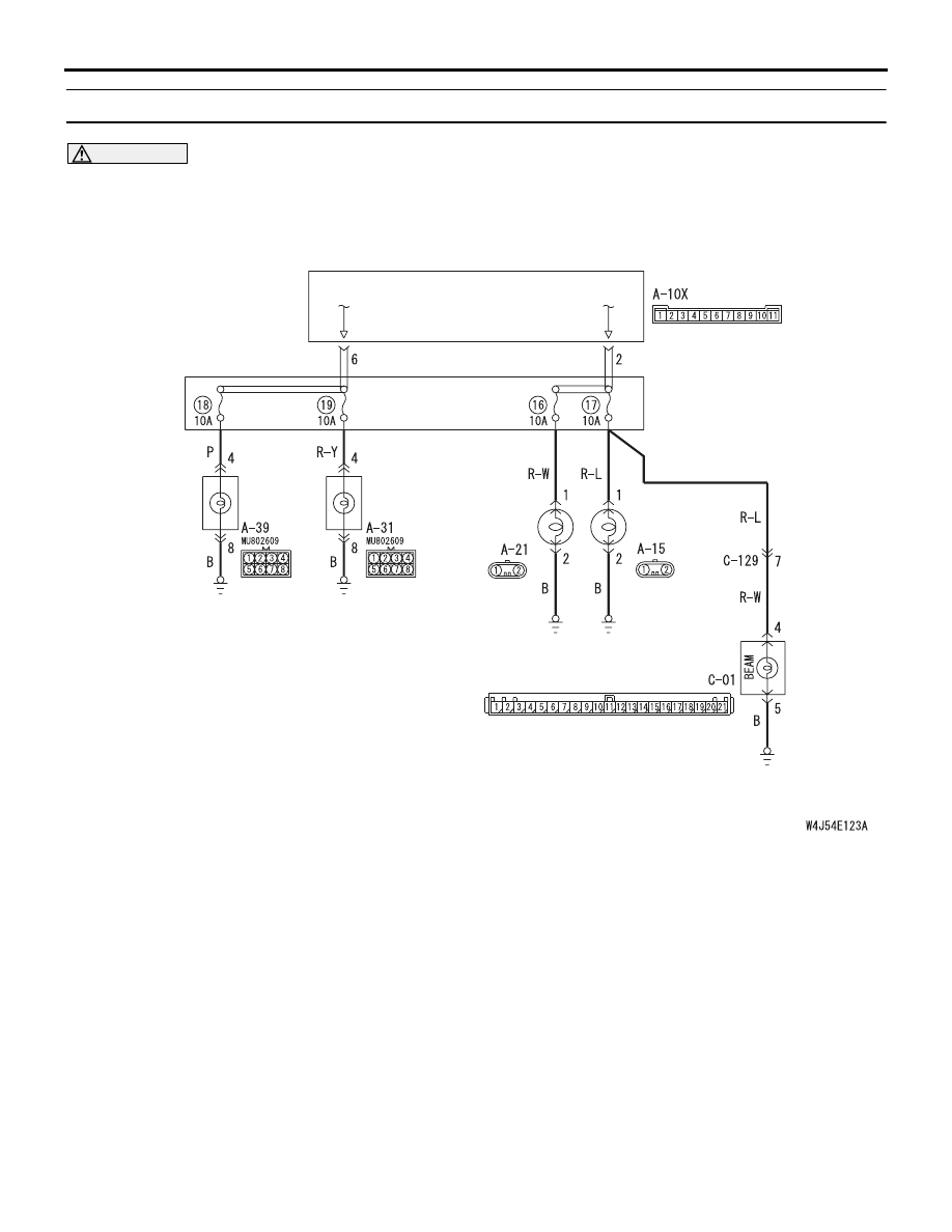
INSPECTION PROCEDURE H-7: The headlamp(s) do not illuminate. <including high-beam indicator>
CAUTION
Whenever the ECU is replaced, ensure that the
input and output signal circuits are normal.
COMMENTS ON TROUBLE SYMPTOM
If any of the headlamps or the high-beam indicator
does not illuminate, the wiring harness connector(s),
the bulb or the fuse may be defective or burned out.
POSSIBLE CAUSES
• Malfunction of the headlamp bulbs
• Malfunction of the high-beam indicator bulb
• Damaged harness wires and connectors
Wire colour code
B : Black LG : Light green G : Green L : Blue W : White Y : Yellow SB : Sky blue
BR : Brown O : Orange GR : Gray R : Red P : Pink V : Violet
HEADLAMP
(HI: RH)
HEADLAMP
(HI: LH)
HEADLAMP
ASSEMBLY
(LH) (LO)
HEADLAMP
ASSEMBLY
(RH) (LO)
COMBINATION
METER
RELAY
BOX
FRONT-ECU
HEADLAMP
RELAY: HI
HEADLAMP
RELAY: LO
Headlamps Circuit
Нет комментариевНе стесняйтесь поделиться с нами вашим ценным мнением.
Текст