Mitsubishi Lancer Evolution IX. Manual — part 423
TROUBLESHOOTING
MULTIPORT FUEL INJECTION (MPI)
13A-167
FUNCTION
• The exhaust camshaft position sensor detects
the top dead center on the compression stroke of
the No. 1 cylinder and inputs a pulse signal to the
engine-ECU.
TROUBLE JUDGMENT
Check Conditions
• Ignition switch: "ON"
• Engine speed of 50 r/min. or more.
Judgment Criterion
• The sensor output voltage remains unchanged
(no pulse signal is inputted) for 2 seconds.
PROBABLE CAUSES
• Failed exhaust camshaft position sensor
• Open/short circuit in exhaust camshaft position
sensor circuit or loose connector contact
• Failed engine-ECU
DIAGNOSIS PROCEDURE
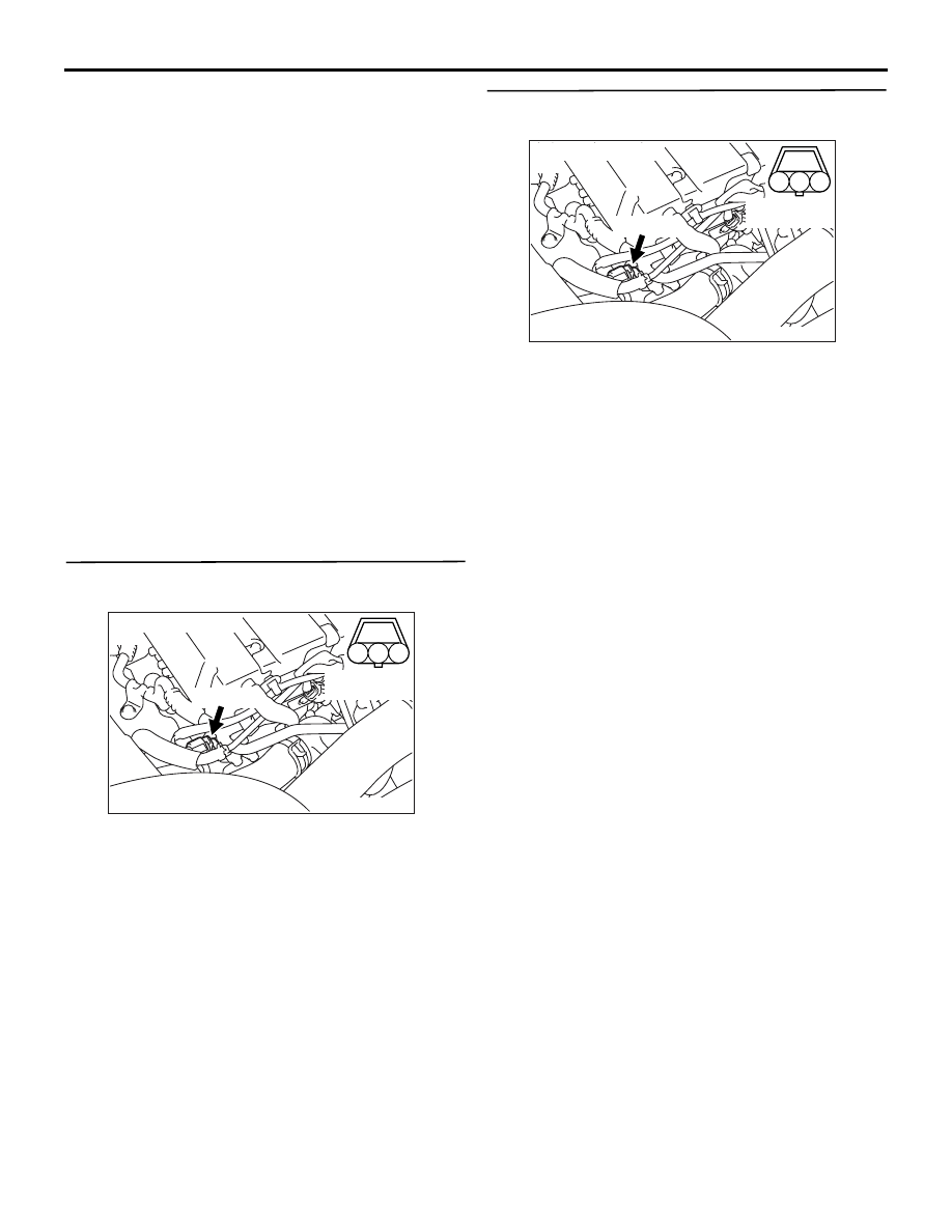
STEP 1. Connector check: B-106 exhaust
camshaft position sensor connector
Q: Is the check result normal?
YES :
Go to Step 2 .
NO :
Repair or replace the connector.
STEP 2. Perform voltage measurement at B-106
exhaust camshaft position sensor connector.
• Disconnect connector, and measure at harness
side.
• Ignition switch: "ON"
• Voltage between terminal No. 3 and earth.
OK: System voltage
Q: Is the check result normal?
YES :
Go to Step 4 .
NO :
Go to Step 3 .
AK501999
1
2
3
AB
Connector: B-106
B-106 (B)
Harness side
connector
AK501999
1
2
3
AB
Connector: B-106
B-106 (B)
Harness side
connector

TROUBLESHOOTING
MULTIPORT FUEL INJECTION (MPI)
13A-168
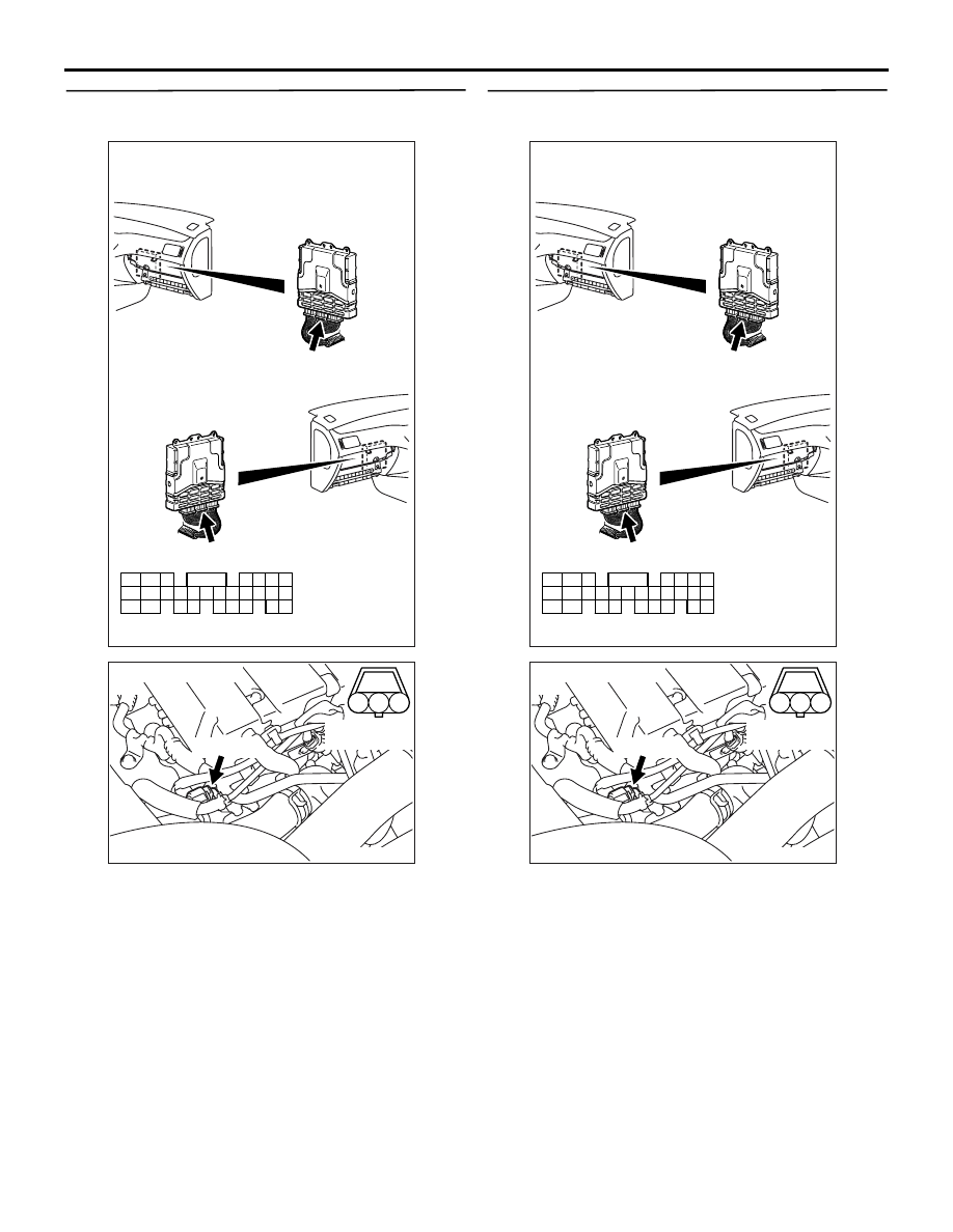
STEP 3. Connector check: B-12X engine control
relay connector
Q: Is the check result normal?
YES :
Check and repair harness between B-106
(terminal No. 3) exhaust camshaft position
sensor connector and B-12X (terminal No.
4) engine control relay connector.
• Check power supply line for
open/short circuit.
NO :
Repair or replace the connector.
STEP 4. Perform voltage measurement at B-106
exhaust camshaft position sensor connector.
• Disconnect connector, and measure at harness
side.
• Ignition switch: "ON"
• Voltage between terminal No. 2 and earth.
OK: 4.9
− 5.1 V
Q: Is the check result normal?
YES :
Go to Step 10 .
NO :
Go to Step 5 .
AK305003
2
1
3
4
AB
Connector : B-12X
B-12X
Harness side
connector
Relay box’s
triangle marks
AK501999
1
2
3
AB
Connector: B-106
B-106 (B)
Harness side
connector
AK501999
1
2
3
AB
Connector: B-106
B-106 (B)
Harness side
connector
TROUBLESHOOTING
MULTIPORT FUEL INJECTION (MPI)
13A-169
STEP 5. Perform voltage measurement at C-119
engine-ECU connector.
• Measure engine-ECU terminal voltage.
• Disconnect B-106 exhaust camshaft position sen-
sor connector.
• Ignition switch: "ON"
• Voltage between terminal No. 50 and earth.
OK: 4.9
− 5.1 V
Q: Is the check result normal?
YES :
Go to Step 6 .
NO :
Go to Step 7 .
STEP 6. Connector check: C-119 engine-ECU
connector
Q: Is the check result normal?
YES :
Check and repair harness between B-106
(terminal No. 2) exhaust camshaft position
sensor connector and C-119 (terminal No.
50) engine-ECU connector.
• Check output line for open circuit.
NO :
Repair or replace the connector.
AK501994
65
43
50
42
49
41
48
60
61
64
46
47
58
59
67
68
45
56
66
52 51
44
53
62
54
63
57
55
AB
Connector: C-119
C-119 (GR)
C-119 (GR)
Harness side connector
<L. H. drive vehicles>
<R. H. drive vehicles>
AK501999
1
2
3
AB
Connector: B-106
B-106 (B)
Harness side
connector
AK501994
65
43
50
42
49
41
48
60
61
64
46
47
58
59
67
68
45
56
66
52 51
44
53
62
54
63
57
55
AB
Connector: C-119
C-119 (GR)
C-119 (GR)
Harness side connector
<L. H. drive vehicles>
<R. H. drive vehicles>
AK501999
1
2
3
AB
Connector: B-106
B-106 (B)
Harness side
connector

TROUBLESHOOTING
MULTIPORT FUEL INJECTION (MPI)
13A-170
STEP 7. Connector check: C-119 engine-ECU
connector
Q: Is the check result normal?
YES :
Go to Step 8 .
NO :
Repair or replace the connector.
STEP 8. Check harness between B-106 (terminal
No. 2) camshaft position sensor connector and
C-119 (terminal No. 50) engine-ECU connector.
• Check output line for short circuit.
Q: Is the check result normal?
YES :
Go to Step 9 .
NO :
Repair the damaged harness wire.
STEP 9. Check the trouble symptoms.
Q: Does trouble symptom persist?
YES :
Replace the engine-ECU.
NO :
Intermittent malfunction (Refer to GROUP
00
− How to Use
Troubleshooting/Inspection Service Points
).
AK501994
65
43
50
42
49
41
48
60
61
64
46
47
58
59
67
68
45
56
66
52 51
44
53
62
54
63
57
55
AB
Connector: C-119
C-119 (GR)
C-119 (GR)
Harness side connector
<L. H. drive vehicles>
<R. H. drive vehicles>
AK501999
1
2
3
AB
Connector: B-106
B-106 (B)
Harness side
connector
AK501994
65
43
50
42
49
41
48
60
61
64
46
47
58
59
67
68
45
56
66
52 51
44
53
62
54
63
57
55
AB
Connector: C-119
C-119 (GR)
C-119 (GR)
Harness side connector
<L. H. drive vehicles>
<R. H. drive vehicles>
Нет комментариевНе стесняйтесь поделиться с нами вашим ценным мнением.
Текст