Mitsubishi Lancer Evolution IX. Manual — part 361

FENDER
BODY
42-5
FENDER
SPECIAL TOOL
M1421000600256
Tool
Number
Name
Use
MB990784
MB990784
Ornament remover
Side turn-signal lamp removal
•
Washer hose (Refer to GROUP 51,
Windshield Wiper and Washer
).
9. Hood support rod
10. Hood heat protector panel
11. Hood heat protector
Hood and hood hinge removal steps
12. Hood outlet garnish
13. Hood hinge bolt (Hood side)
14. Hood
15. Shim
16. Hood hinge
17. Hood weather strip
Hood and hood hinge removal steps
FENDER
BODY
42-6
FENDER
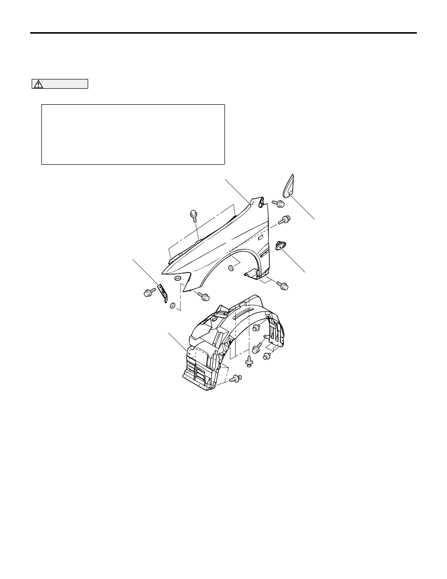
REMOVAL AND INSTALLATION
M1421001900409
CAUTION
Use the special fasteners to secure the fender. They have special coating for anti-corrosion.
Pre-removal and Post-installation Operation
• Front Bumper Assembly Removal and Installation (Refer
to GROUP 51, Front Bumper Assembly
).
• Front Deck Garnish Removal and Installation (Refer to
GROUP 51, Windshield Wiper and Washer
• Side Air Dam Removal and Installation (Refer to GROUP
51, Side Air Dam
AC211637
1
5
2
3
4
AB
Removal steps
1. Splash shield
<<
A
>> >>
A
<< 2. Side turn-signal lamp
3. Delta garnish (Refer to GROUP 51,
Garnish and Moulding
).
4. Fender
5. Front fender bracket
Removal steps (Continued)

FENDER
BODY
42-7
REMOVAL SERVICE POINT
<<A>> SIDE TURN-SIGNAL LAMP
REMOVAL
AC005980
AC005980
Front of vehicle
Side turn-signal lamp
MB990784
AD
Use special tool ornament remover (MB990784) to
prize out the tab from the fender, and remove the
side turn-signal lamp.
INSTALLATION SERVICE POINT
>>A<< SIDE TURN-SIGNAL LAMP
INSTALLATION
AC005719
Fender
Hook
Claw
Fender
: Front of vehicle
AB
Engage the claw with the fender, and install the side
turn-signal lamp.

FUEL FILLER LID
BODY
42-8
FUEL FILLER LID
REMOVAL AND INSTALLATION
M1421002500277
Pre-removal and Post-installation Operation
• Rear Seat Removal and Installation (Refer to GROUP
52A, Rear Seat
• Front Scuff Plate (Driver's Seat Side), Rear Scuff Plate
(Driver's Side), Centre Pillar Lower Trim (Driver's Side),
Quarter Trim (Driver's Side) Removal and Installation
(Refer to GROUP 52A, Trims
18M0109
W0570AQ
AC005996
AC005973
3
5
4
3
2
1
5.0 ± 1.0 N·m
AC
Fuel filler lid height and clearance
adjustment
Removal steps
1.
Fuel filler lid panel assembly
2.
Clip
3.
Fuel filler lid hook assembly
4.
Fuel filler lid lock release cable
5.
Fuel filler lid lock release handle
Removal steps (Continued)
Нет комментариевНе стесняйтесь поделиться с нами вашим ценным мнением.
Текст