Mitsubishi Lancer Evolution IX. Manual — part 520

TROUBLESHOOTING
ANTI-SKID BRAKING SYSTEM (ABS)
35B-111
Q: Are the connectors and terminals in good
condition?
YES :
Go to Step 3.
NO :
Repair it and then go to Step 7.
STEP 3. Check the following harness wire.
The wire between diagnosis connector C-14 (termi-
nal 16) and junction block connector C-212 (terminal
1)
Q: Is the harness wire damaged?
YES :
Repair or replace it and then go to Step 7.
NO :
Go to Step 7.
STEP 4. Check the earth circuit. Resistance
measurement at diagnosis connector C-14.
Measure the resistance between terminal 4 and
earth, and terminal 5 and earth.
OK: 2 ohms or less
Q: Is the resistance 2 ohms or less?
YES :
Replace the M.U.T.-II/III and then go to Step
7.
NO :
Go to Step 5.
STEP 5. Check the following connector.
•
Diagnosis connector C-14
Check the connector, for loose, corroded or dam-
aged terminals, or terminals pushed back in the con-
nector.
Q: Are the connector and terminals in good
condition?
YES :
Go to Step 6.
NO :
Repair it and then go to Step 7.
AC311202 AB
C-14(B)
Connector: C-14
AC311165
Connector: C-212
AC
Junction block
(Front view)
C-212 (B)
Harness side
1
AC311203AC
Diagnosis connector
C-14(B)
Connector: C-14
AC311202 AB
C-14(B)
Connector: C-14

TROUBLESHOOTING
ANTI-SKID BRAKING SYSTEM (ABS)
35B-112
STEP 6. Check the following harness wires.
•
The wire between diagnosis connector C-14 (termi-
nal 4) and earth
• The wire between diagnosis connector C-14 (ter-
minal 5) and earth
Q: Is any harness wire damaged?
YES :
Repair or replace it and then go to Step 7.
NO :
Go to Step 7.
STEP 7. Retest the system.
Q: Does the M.U.T.-II/III communicate with the whole
system?
YES :
The procedure is complete.
NO :
Return to Step 1.
AC311202 AB
C-14(B)
Connector: C-14
AC311200AB
Earth
Windshield
wiper arm
TROUBLESHOOTING
ANTI-SKID BRAKING SYSTEM (ABS)
35B-113
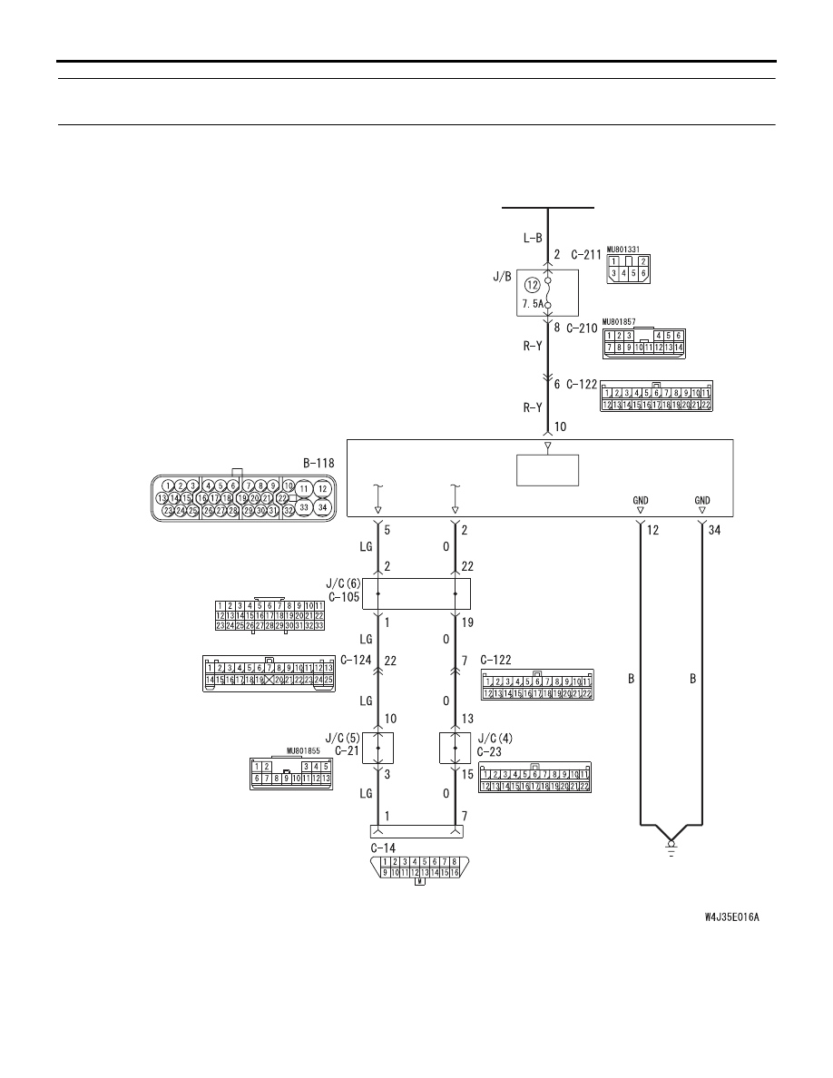
INSPECTION PROCEDURE 2: Communication between the M.U.T.-II/III and the ABS-ECU is not
possible.
OPERATION
• The diagnosis code is set by the ABS-ECU (ter-
minal 2) to the diagnostic output terminal (termi-
nal 7) of the diagnosis connector.
• When the diagnosis connector's diagnosis test
mode control terminal (terminal 1) is earthed, the
ABS-ECU will go into diagnosis mode.
ABS-ECU
DIAGNOSIS
CONNECTOR
FRONT SIDE
IGNITION
SWITCH (IG2)
POWER
SUPPLY
Wire colour code
B : Black LG : Light green
G : Green L : Blue
W : White Y : Yellow
SB : Sky blue BR : Brown
O : Orange GR : Gray
R : Red P : Pink V : Violet
ABS-ECU Power Supply /Earth and Diagnosis Connector Circuit
TROUBLESHOOTING
ANTI-SKID BRAKING SYSTEM (ABS)
35B-114
COMMENT ON TROUBLE SYMPTOM
When communication with the M.U.T.-II/III is not pos-
sible, the cause is probably an open circuit in the
ABS-ECU power circuit or an open circuit in the diag-
nostic output circuit.
PROBABLE CAUSES
The most likely causes for this case are:
• Blown fuse
• Damaged wiring harness or connector
• Malfunction of the brake modulator hydraulic unit
(Integrated with ABS-ECU)
DIAGNOSIS
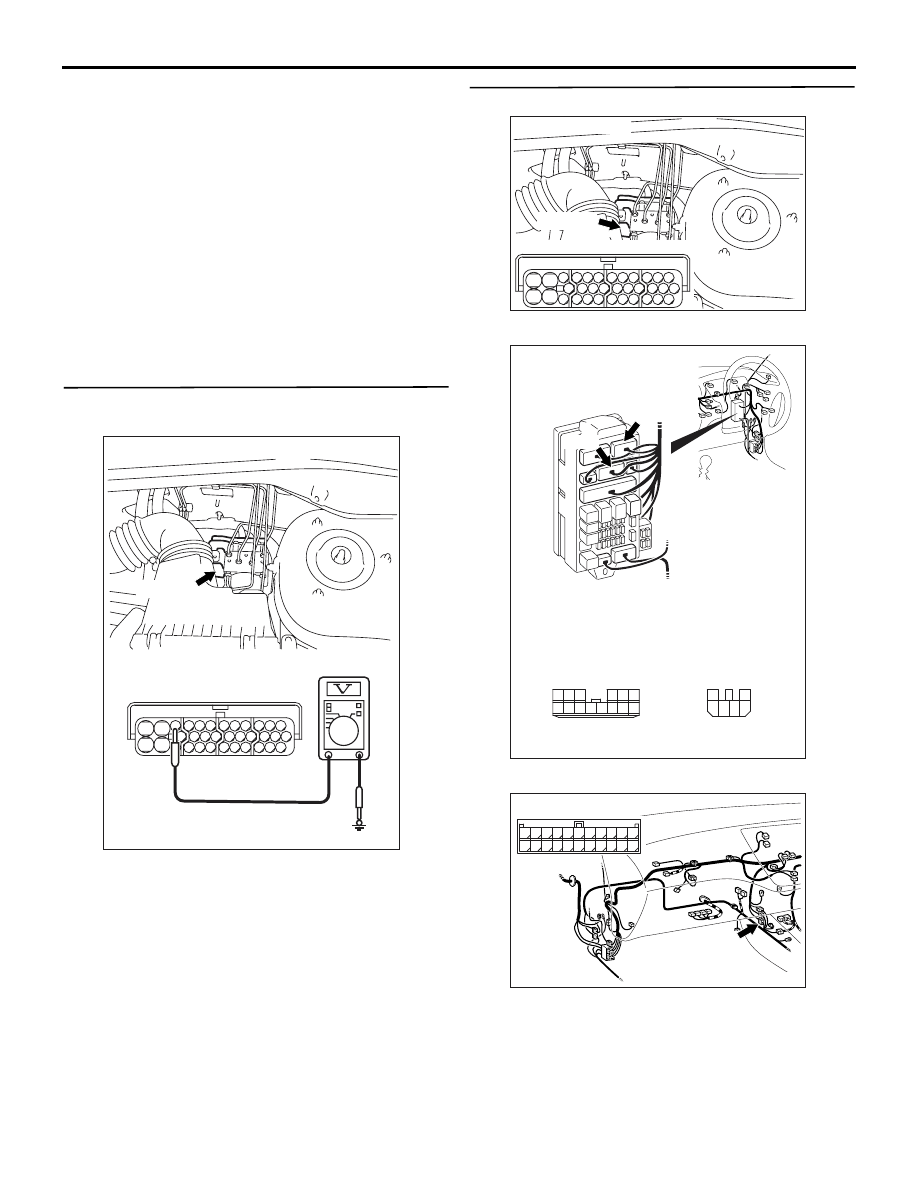
STEP 1. Check the power supply circuit. Voltage
measurement at ABS-ECU connector B-118.
(1) Disconnect ABS-ECU connector B-118 and
measure at the harness side.
(2) Start the engine.
(3) Measure the voltage between terminal 10 and
earth.
OK: System voltage
Q: Is the check result normal?
YES :
Go to Step 4.
NO :
Go to Step 2.
STEP 2. Check the following connectors.
•
ABS-ECU connector B-118
•
Junction block connectors C-210, C-211
•
Intermediate connector C-122
Check the connectors for loose, corroded or dam-
aged terminals, or terminals pushed back in the con-
nector.
AC311168AC
B-118 (B)
Connector: B-118
28
32
34
12
11
33
30
21
9
10
22
31
7
8
29
20 19
24
2
26
4
5
6
27
18 17
3
25
16 15
1
23
13
14
Connector B-118
(harness side)
AC311127AB
B-118 (B)
Connector: B-118
28
32
34
12
11
33
30
21
9
10
22
31
7
8
29
20 19
24
2
26
4
5
6
27
18 17
3
25
16 15
1
23
13
14
Harness side
AC311164
Connectors: C-210, C-211
C-210
C-211
AB
Junction block
(Front view)
Connector C-210
(Harness side)
4
6 5
3
2
1
10
1
6
14
5
12
13
4
11
7
2
3
8
9
Connector C-211
(Harness side)
AC311160AC
Connector: C-122
C-122 (L)
2
1
3
13
12
14
21
10
5
4
6
16
15
17
7 8 9
19
18
20
11
22
Нет комментариевНе стесняйтесь поделиться с нами вашим ценным мнением.
Текст