Mitsubishi Montero (1991+). Manual — part 106
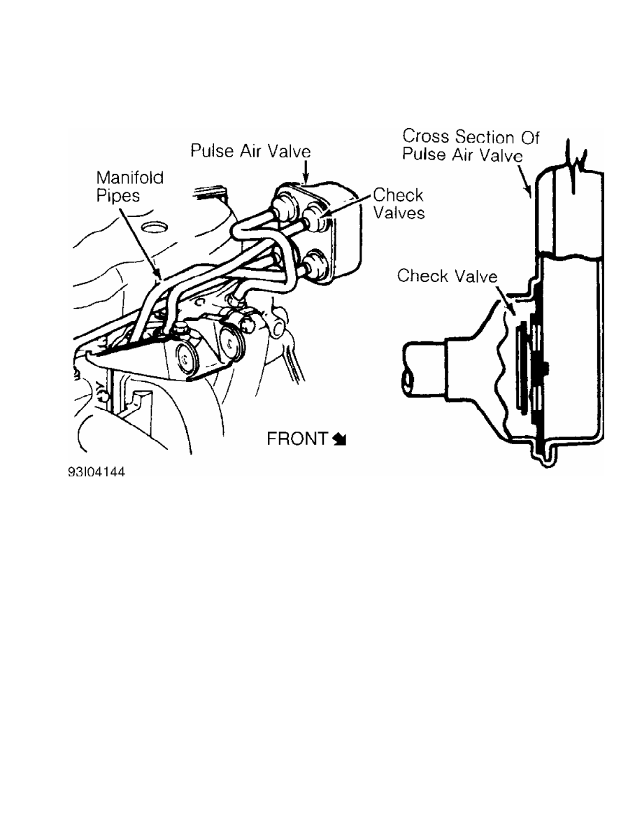
Fig. 14: Typical Pulsed Secondary Air Injection System
Courtesy of General Motors Corp.
OXYGEN SENSOR (O2)
The O2 sensor is mounted in the exhaust system where it
monitors oxygen content of exhaust gases. Some vehicles may use 2 O2
sensors. The O2 sensor produces a voltage signal which is proportional
to exhaust gas oxygen concentration (0-3%) compared to outside oxygen
(20-21%). This voltage signal is low (about .1 volt) when a lean
mixture is present and high (1.0 volt) when a rich mixture is present.
As ECM compensates for a lean or rich condition, this voltage
signal constantly fluctuates between high and low, crossing a
reference voltage supplied by the ECM on the O2 signal line. This is
referred to as cross counts. A problem in the O2 sensor circuit should
set a related trouble code.
COMPUTERIZED ENGINE CONTROLS (CEC)
The CEC system monitors and controls a variety of
engine/vehicle functions. The CEC system is primarily an emission
control system designed to maintain a 14.7:1 air/fuel ratio under most
operating conditions. When the ideal air/fuel ratio is maintained, the
catalytic converter can control oxides of nitrogen (NOx), hydrocarbon
(HC) and carbon monoxide (CO) emissions.
The CEC system consists of the following sub-systems:
Electronic Control Module (ECM), input devices (sensors and switches)
and output signals.
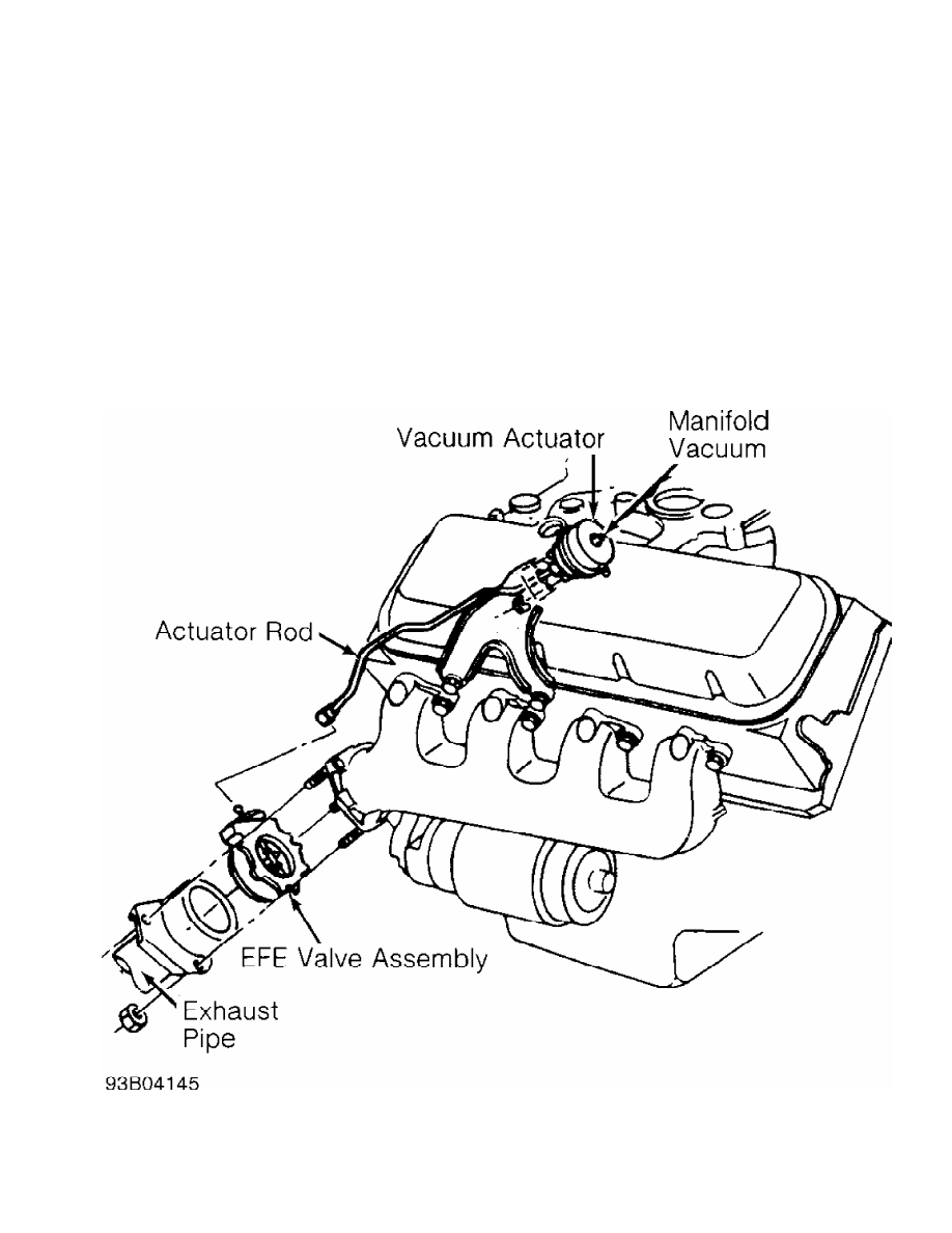
EARLY FUEL EVAPORATION (EFE)
The EFE valve is actuated by either a vacuum actuator or a
bimetal spring (heat-riser type). The EFE valve is closed when engine
is cold. The closed valve restricts exhaust gas flow from the exhaust
manifold. This forces part of the exhaust gas to flow up through a
passage below the carburetor. As the exhaust gas quickly warms the
intake mixture, distribution is improved. This results in better cold
engine driveability, shorter choke periods and lower emissions.
Ensure EFE valve in exhaust manifold is not frozen or rusted
in a fixed position. On vacuum-actuated EFE system, check EFE thermal
vacuum valve and check valve(s). Also check for proper vacuum hose
routing. See Fig. 15.
Fig. 15: Typical Vacuum-Actuated EFE System
Courtesy of General Motors Corp.
EMISSION MAINTENANCE REMINDER LIGHT (EMR) (IF EQUIPPED)
If equipped, the EMR light (some models may use a reminder
flag) reminds vehicle operator that an emission system maintenance is
required. This indicator is activated after a predetermined
time/mileage.
When performing a smog check inspection, ensure EMR indicator
is not activated. On models using an EMR light, light should glow when
ignition switch is turned to ON position and should turn off when
engine is running.
If an EMR flag is present or an EMR light stays on with
engine running, fail vehicle and service or replace applicable
emission-related components. To reset an EMR indicator, refer to
appropriate MAINTENANCE REMINDER LIGHTS in the MAINTENANCE section.
MALFUNCTION INDICATOR LIGHT (MIL)
The Malfunction Indicator Light (MIL) is used to alert
vehicle operator that the computerized engine control system has
detected a malfunction (when it stays on all the time with engine
running). On some models, the MIL may also be used to display trouble
codes.
As a bulb and system check, malfunction indicator light will
glow when ignition switch is turned to ON position and engine is not
running. When engine is started, light should go out.
ENGINE COOLING FAN
1991 Mitsubishi Montero
1991 ENGINE COOLING
Mitsubishi Engine Cooling Fans
Mitsubishi: Eclipse, Galant, Mirage,
Montero, Pickup, Precis, 3000GT
ELECTRIC COOLING FAN - COMPONENT TESTING
MOTOR
Disconnect electric cooling fan motor at junction. Using 2
jumper wires, ground one lead and apply battery voltage to other. Fan
should rotate. If fan does not rotate, replace motor.
RADIATOR FAN SWITCH
Using an ohmmeter, check switch continuity in hot water.
Switch should be open at less than 180 F (82 C) and continuity should
exist at more than 185 F (85 C). Replace radiator fan switch if it
does not test as specified.
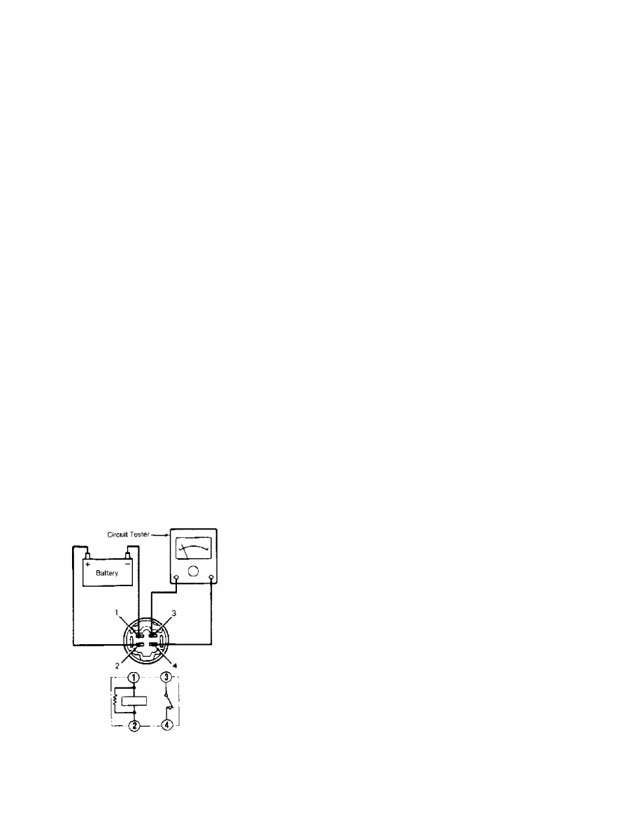
ELECTRIC COOLING FAN RELAY
1) Remove relay from relay box in front of right suspension
tower. Using jumper wires, connect battery to indicated terminals.
2) On 3000GT, continuity should exist between terminals No. 1
and 3. With battery disconnected, continuity should exist between
terminals No. 2 and 4 and should not exist between terminals No. 1 and
3.
3) On all other models, continuity should exist between
terminals No. 3 and 4. With battery disconnected, continuity should
exist between terminals No. 1 and 2 and should not exist between
terminals No. 3 and 4. Replace relay if it does not test as specified.
Fig. 1: Testing Electric Cooling Fan Relay (except 3000GT)
Courtesy of Mitsubishi Motor Sales of America.
Нет комментариевНе стесняйтесь поделиться с нами вашим ценным мнением.
Текст