Mitsubishi Montero (1991+). Manual — part 8
.012" (.3 mm) Oversize . . . .311-.319 (7.9-8.1)
.024" (.6 mm) Oversize . . . .323-.331 (8.2-8.4)
Bore Diameter
.012" (.3 mm) Oversize .. 1.3110-1.3120 (33.300-33.325)
.024" (.6 mm) Oversize .. 1.3228-1.3238 (33.600-33.625)
VALVES
Disassemble cylinder head. Measure valve stem diameter, valve
margin and overall length. Replace valves if not within specification.
See appropriate VALVES & VALVE SPRINGS table under ENGINE
SPECIFICATIONS at end of article. Check valve for worn valve tip.
Measure valve margin after grinding valves.
LASH ADJUSTERS
Before installation, submerge lash adjuster in diesel fuel.
Using a small wire, hold down internal check valve. Pump plunger up
and down 4 or 5 times to bleed air from lash adjuster.
CYLINDER BLOCK ASSEMBLY OVERHAUL
CYLINDER BLOCK
1) Inspect cylinder block for cracks, warpage, cylinder bore
taper and out-of-round. Replace or repair cylinder block if it is not
within specification. See CYLINDER BLOCK table under ENGINE
SPECIFICATIONS at end of article.
2) Measure cylinder bore and piston skirt diameter. Piston
skirt diameter should be measured at 90-degree angle to piston pin.
Clearance between piston and cylinder bore must be within
specification. See appropriate PISTONS, PINS & RINGS table under
ENGINE SPECIFICATIONS at end of article.
PISTON & ROD ASSEMBLY
1) Remove cylinder heads, and remove oil pan. See CYLINDER
HEADS and OIL PAN under REMOVAL & INSTALLATION. Ensure cylinder ridge
is removed. Mark connecting rod and cap for cylinder identification.
2) Note front mark on piston and connecting rod. See Fig. 23.
Mark is positioned toward timing belt side of engine. Remove rod cap
and piston assembly.
3) Ensure piston ring end gap and side clearance are within
specification. See appropriate PISTONS, PINS & RINGS table under
ENGINE SPECIFICATIONS at end of article. Install rings on piston with
ring code identification marks toward top of piston. On DOHC, top ring
is marked "T" and No. 2 ring is marked "T2". On SOHC, top ring is
marked "T1" and No. 2 ring is marked "2R". Lubricate piston, rings and
cylinder bore with engine oil.
4) Properly space ring end gaps on piston. See Fig. 23.
Install piston and rod into cylinder bore. Ensure piston is installed
with front mark toward timing belt side of engine.
NOTE: Front mark "R" on piston indicates installation in
cylinders No. 1, 3 or 5 while front mark "L" indicates
installation in cylinders No. 2, 4 or 6. Ensure front mark
on piston and connecting rod are toward timing belt side of
engine. See Fig. 23.
5) Check bearing clearance using Plastigage method. Tighten
rod cap nuts to specification. See appropriate TORQUE SPECIFICATIONS

table at end of article. Ensure rod moves freely on crankshaft. Check
connecting rod side play. Repair or replace connecting rod if not
within specification. See CONNECTING RODS table under ENGINE
SPECIFICATIONS at end of article.
Fig. 23: Aligning Piston & Rings
Courtesy of Mitsubishi Motor Sales of America, Inc.
FITTING PISTONS
Measure cylinder bore and piston skirt diameter. Piston skirt
diameter should be measured at 90-degree angle to piston pin.
Clearance between piston and cylinder bore must be within
specification. See appropriate PISTONS, PINS & RINGS table under
ENGINE SPECIFICATIONS at end of article.
PISTON PIN REPLACEMENT
1) Note reference mark on top of piston and connecting rod.
See Fig. 23. Using press and Piston Pin Remover/Installer (MD998184
for SOHC or MD998765 for DOHC), remove pin.
2) Inspect piston for cracks and damage. Check ring side
clearance. Replace piston if not within specification. See appropriate
PISTONS, PINS & RINGS table under ENGINE SPECIFICATIONS.
3) Check connecting rod for bend and twist. Replace
connecting rod if twist exceeds .004" (.10 mm) or bend exceeds .002"
(.05 mm). Pressure required to install pin in rod is 1686-3934 lbs.
(7500-17,500 N).
4) Position piston on connecting rod. Ensure reference marks
on top of piston and connecting rod are aligned. See Fig. 23.
Lubricate all components with oil. To install, reverse removal
procedure. Ensure piston pin is centered in piston.
NOTE: Install piston with reference mark aligned with connecting
rod reference mark. See Fig. 23.
CRANKSHAFT & MAIN BEARINGS
1) Remove flywheel or drive plate. Remove
transaxle/transmission mounting plate and rear seal case. Remove oil
pump, oil pan and oil pick-up tube. Ensure connecting rods and main
bearing cap are marked for location.
2) Remove connecting rod caps and bearings. Note direction of
arrow on main bearing cap. Remove main bearing cap. See Fig. 24.
Ensure all components are placed in correct order. Remove crankshaft.
Remove main bearings from cylinder block. Mark bearings for location.
3) Inspect crankshaft for cracks and damaged gear or threads.
Check crankshaft for taper and out-of-round. Replace or repair
crankshaft if it is not within specification. See CRANKSHAFT, MAIN &
CONNECTING ROD BEARINGS table under ENGINE SPECIFICATIONS at end of
article.
4) Install upper main bearings in cylinder block. Ensure oil
hole is aligned and bearing is properly seated. Lubricate bearings
with engine oil. Install thrust bearings on No. 3 main bearing journal
with oil grooves toward crankshaft thrust surface.
5) Install crankshaft in block. Install thrust bearing on No.
3 main bearing cap with oil grooves toward crankshaft thrust surface.
Install main bearing cap with arrow toward front of engine.
6) Check oil clearance using Plastigage method. Tighten bolts
to specification in proper sequence. See Fig. 24. See appropriate
TORQUE SPECIFICATIONS table at end of article. Remove main bearing
cap. Clearance must be within specification. See CRANKSHAFT, MAIN &
CONNECTING ROD BEARINGS table. If oil clearance exceeds specification,
replace bearings or crankshaft.
7) Ensure crankshaft rotates freely with main bearing cap
installed. Check crankshaft end play. See CRANKSHAFT, MAIN &
CONNECTING ROD BEARINGS table.
8) Install connecting rod caps and bearings. Ensure
components are installed in original location. Tighten rod nuts to
specification. See appropriate TORQUE SPECIFICATIONS table. Ensure
connecting rods move freely on crankshaft. To complete installation,
reverse removal procedure. Tighten bolts to specification.
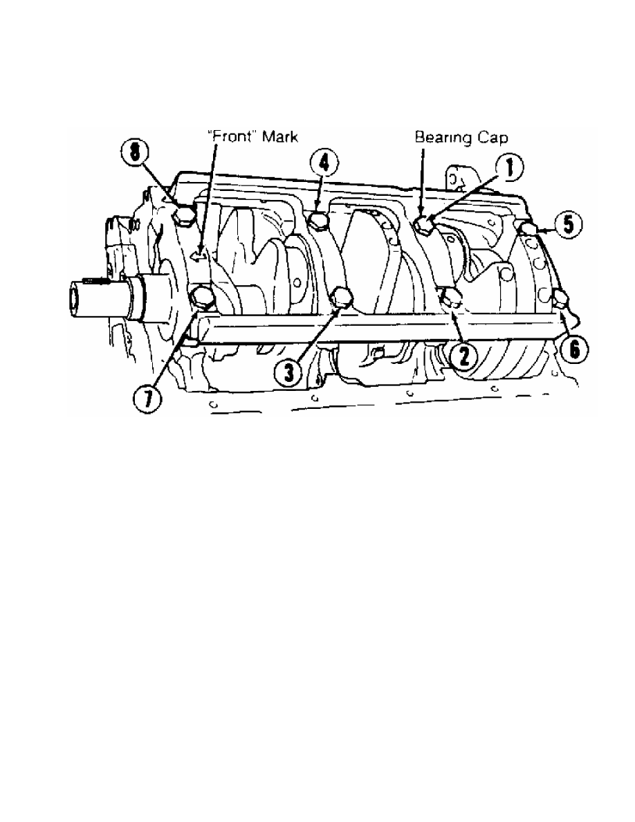
Fig. 24: Main Bearing Cap Bolt Tightening Sequence
Courtesy of Mitsubishi Motor Sales of America, Inc.
CONNECTING ROD BEARINGS
1) Mark bearing cap and connecting rod for location. Remove
connecting rod cap and bearing. Install replacement bearing.
2) Ensure reference marks on rod cap and connecting rod are
aligned. Check bearing clearance using Plastigage method. Ensure
connecting rod moves freely on crankshaft. Check connecting rod side
play. See CONNECTING RODS table under ENGINE SPECIFICATIONS at end of
article.
CRANKSHAFT END PLAY
If end play is not within specification, inspect thrust
bearings and crankshaft. Replace thrust bearing or crankshaft to
obtain correct end play. See CRANKSHAFT, MAIN & CONNECTING ROD
BEARINGS table under ENGINE SPECIFICATIONS at end of article.
ENGINE OILING
ENGINE LUBRICATION SYSTEM
Oil pressure is provided by a rotor-type pump driven by
crankshaft. Pressure relief valve is located in oil pump body.
CRANKCASE CAPACITY
Montero & Pick-up oil capacity is 5.0 qts. (4.7L). Add .5 qt.
(.4L) with filter replacement. Add .5 qt. (.4L) with oil cooler.
3000GT oil capacity is 4.2 qts. (4.0L). Add .5 qt. (.4L) with filter
replacement. Add .5 qt. (.4L) with oil cooler.
Нет комментариевНе стесняйтесь поделиться с нами вашим ценным мнением.
Текст