Mitsubishi Montero (1991+). Manual — part 14
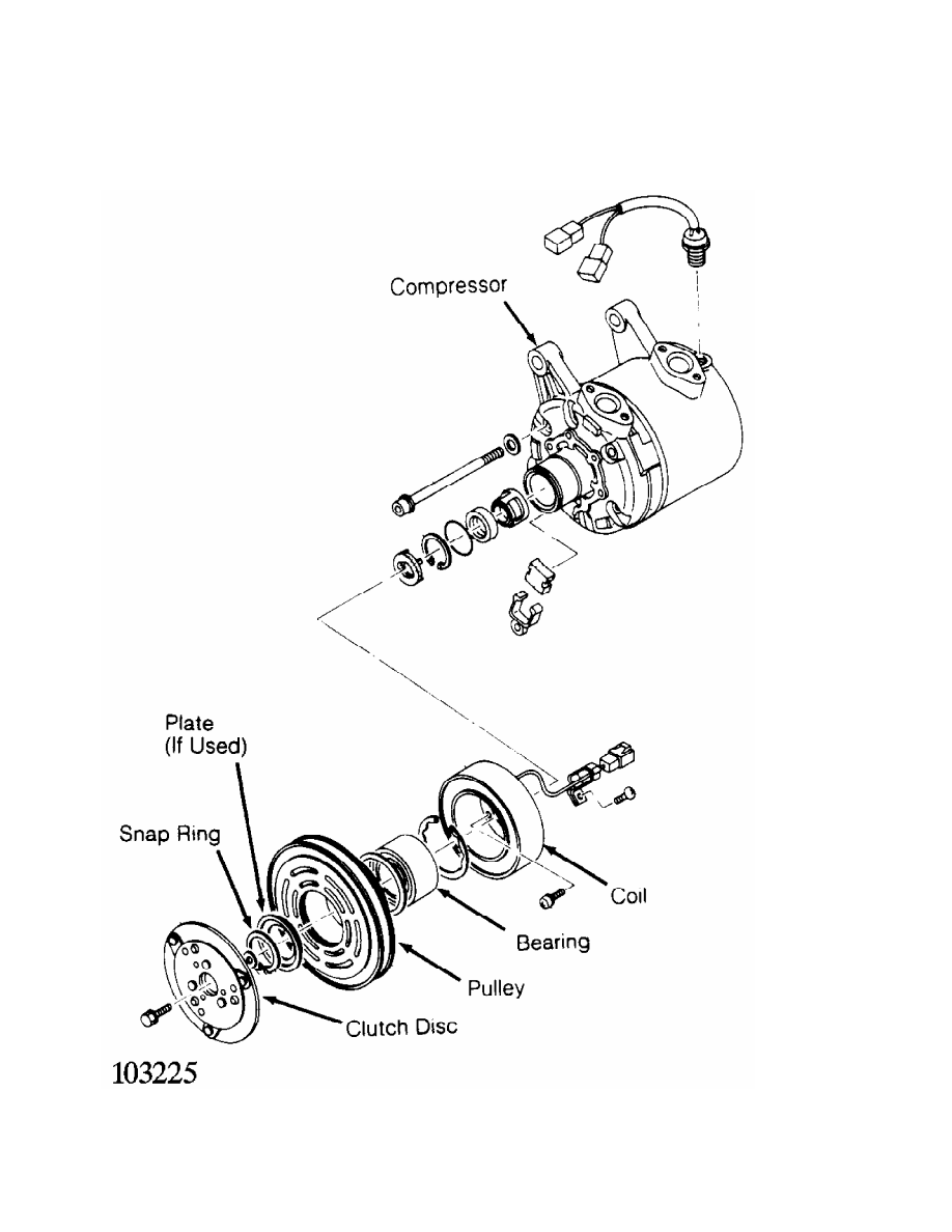
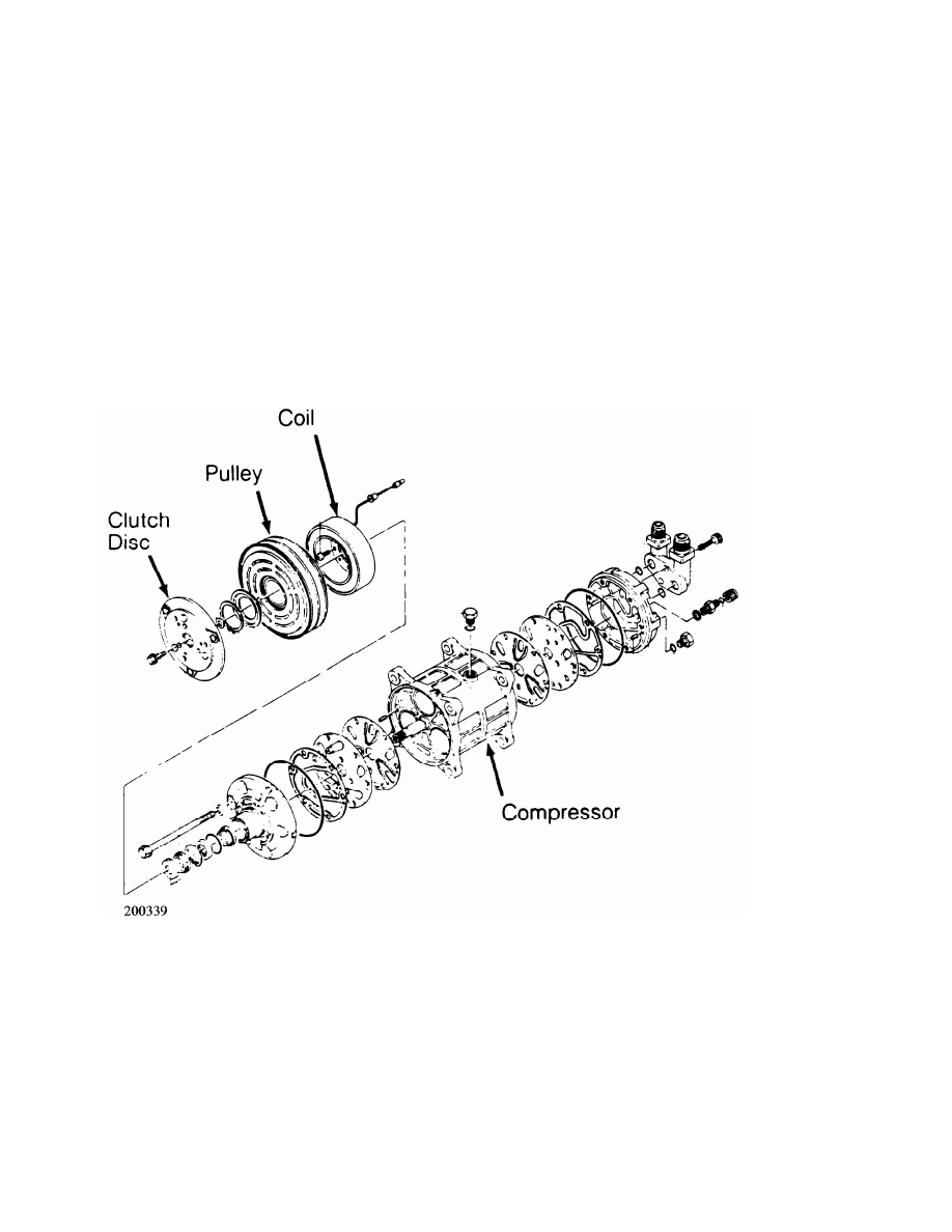
Fig. 4: Diesel Kiki Rotary Vane Compressor
Courtesy of Nissan Motor Co., U.S.A.
DIESEL KIKI 6-CYL SHAFT SEAL R & I
Removal & Installation
1) Remove clutch coil assembly. Remove retainer and felt.
Discard retainer and felt. Using internal snap ring pliers, remove
seal seat snap ring. Remove seal seat and discard. Using a seal pick,
remove "O" ring from inside groove of shaft seal housing. Discard "O"
ring.
2) To remove shaft seal, push down and turn clockwise on seal
remover to engage tangs. Slowly draw seal from bore. Discard seal.
Check shaft and inside of compressor neck for dirt or foreign material
and ensure these areas are perfectly clean before installing new seal.
3) To install, reverse removal procedure. Coat "O" ring,
shaft seal, and seal seat with new refrigerant oil.
Fig. 5: Diesel Kiki 6-Cylinder Compressor
Courtesy of Mitsubishi Motor Sales of America.
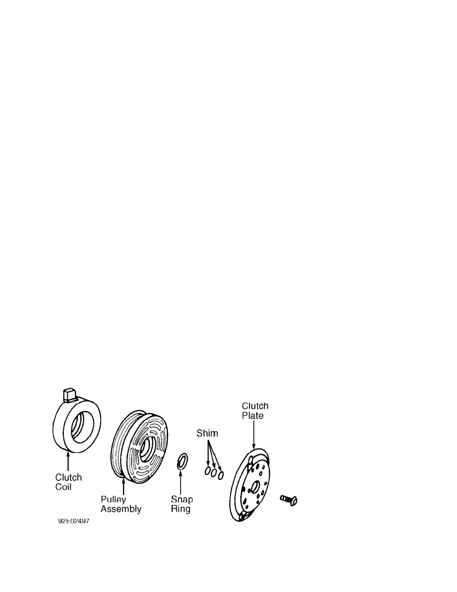
FORD FX-15 CLUTCH R & I
Removal
1) Using Clutch Holder (00 41 0812 05), remove clutch plate
retaining bolt and discard. Using an 8 mm bolt threaded into clutch
plate, remove clutch plate and shim(s). See Fig. 6.
2) Remove snap ring and pulley assembly. Install Shaft
Protector (49 UN01 47) over shaft seal opening. Use a 2-jaw puller to
remove clutch coil from compressor.
Installation
1) Ensure clutch coil mounting surface is clean. Use Coil
Installer (49 UN01 046) and 2-jaw puller engaged to rear side of
compressor front mounts to press coil into place.
2) Install pulley assembly. Install pulley assembly snap ring
with bevel side of snap ring facing out. Install shim(s) and clutch
plate. Install a NEW clutch plate retaining bolt and tighten to
96-120 INCH lbs. (11-14 N.m).
3) Use a feeler gauge to check clearance between clutch plate
and pulley assembly. Clearance should be .018-.033" (.46-.84 mm). If
clearance is incorrect, add or remove shims as necessary.
FORD FX-15 SHAFT SEAL R & I
Removal
1) Using Clutch Holder (000 41 0812 05), remove clutch plate
retaining bolt and discard. Using an 8 mm bolt threaded into clutch
plate, remove clutch plate and shim(s). See Fig. 6.
2) Remove shaft felt seal. Thoroughly clean seal area of
compressor. Remove shaft seal retaining snap ring. Position Shaft Seal
Remover (49 UN01 044) over compressor shaft.
3) Push shaft seal remover downward against seal. Ensure end
of shaft seal remover is engaged with inside of seal. Rotate shaft
seal remover clockwise to expand remover tip inside seal. Pull shaft
seal from compressor.
Installation
1) Lubricate shaft seal protector and shaft seal with
refrigerant oil. Install shaft seal on shaft seal protector so lip
seal is toward compressor (large end of shaft seal protector).
2) Install shaft seal protector on compressor shaft. Using
shaft seal installer (49 UN01 043), push shaft seal down seal
protector until seal is seated.
3) Remove shaft seal installer and protector. Install a NEW
shaft seal retaining snap ring and shaft seal felt. Install shim(s)
and clutch plate. Install a NEW clutch plate retaining bolt and
tighten to 91-120 INCH lbs. (11-14 N.m).
4) Use a feeler gauge to check clearance between clutch plate
and pulley assembly. Clearance should be .018-.033" (.46-.84 mm). If
clearance is incorrect, add or remove shims as necessary.
Fig. 6: Exploded View of Compressor Clutch (Ford FX-15)
Courtesy of Mazda Motors Corp.
HARRISON R4 4-CYL CLUTCH R & I
Removal
1) Clamp Holding Fixture (J-25008-A) in a vise and attach
compressor to holding fixture with thumb screws. Use Clutch Hub Holder
(J-33027) to hold clutch. Remove shaft nut using Shaft Nut Socket (J-
9399).
2) Thread Clutch Plate and Hub Assembly Remover (J-33013-B)
into hub. Hold body of remover with a wrench and turn center screw
into remover body to remove clutch plate and hub assembly. Remove
shaft key and retain for assembly. See Fig. 5.
NOTE: DO NOT drive or pound on clutch hub or shaft.
Installation
1) Install shaft key into hub key groove. Allow key to
project approximately 1/8" out of key way. Shaft key is curved
slightly to provide an interference fit in hub key groove.
2) Ensure frictional surface of clutch plate and clutch rotor
are clean before installing clutch plate and hub assembly. Align shaft
key with shaft key way and place clutch plate and hub assembly onto
compressor shaft.
3) Hold hex portion of Installer (J-9480-B) with a wrench.
Tighten center screw to press hub into shaft until there is .020-.040"
(.5-1.0 mm) air gap between frictional plate and clutch rotor.
4) Install new shaft nut with small diameter boss of nut
against crankshaft shoulder. Use Thin Wall Socket (J-9399) and Clutch
Hub Holder (J-25030). Tighten shaft nut to 10 ft. lbs. (14 N.m). Spin
pulley rotor by hand to ensure rotor is not rubbing on clutch drive
plate.
HARRISON R4 4-CYL SHAFT SEAL R & I
Removal
1) Clamp Holding Fixture (J-25008-A) in a vise and attach
compressor to holding fixture with thumb screws. Use Clutch Hub Holder
(J-33027) to hold clutch. Remove shaft nut using Shaft Nut Socket (J-
9399).
2) Thread Clutch Plate and Hub Assembly Remover (J-33013-B)
into hub. Hold body of remover with a wrench and turn center screw
into remover body to remove clutch plate and hub assembly. Remove
clutch plate and shaft key. Pry out dust seal (if equipped). Remove
seal seat snap ring. Thoroughly clean compressor neck area and "O"
ring groove surrounding shaft. Any dirt or foreign material may cause
compressor damage.
3) Use Seal Remover/Installer (J23128-A), remove seal with a
twisting motion. Use "O" Ring Remover (J-9553-01) to remove "O" ring.
Installation
1) Coat new shaft seal with refrigerant oil and install shaft
seal on remover/installer. Align compressor shaft machined surface
with shaft seal and install. Turn remover/installer slightly
counterclockwise to secure shaft seal tangs.
2) Using Seal Installer (J-33011), install "O" ring and coat
with refrigerant oil. Coat seal seat with refrigerant oil and install
using seal seat remover/installer. Install snap ring. Install dust
seal (if supplied in seal kit). See Fig. 7.
Нет комментариевНе стесняйтесь поделиться с нами вашим ценным мнением.
Текст