Mitsubishi Montero (1991+). Manual — part 110
Install head bolts. Head bolts should be tightened in proper
steps and sequence to specification. See Fig. 1. Install remaining
components. Tighten all bolts to specification. Adjust valves if
required. See VALVE ADJUSTMENT in this article.
NOTE: Some manufacturers require that head bolts be retightened
after specified amount of operation. This must be done to
prevent head gasket failure.
VALVE ADJUSTMENT
Engine specifications will indicate valve train clearance and
temperature at which adjustment is to be made on most models. In most
cases, adjustment will be made with a cold engine. In some cases, both
a cold and a hot clearance will be given for maintenance convenience.
On some models, adjustment is not required. Rocker arms are
tightened to specification and valve lash is automatically set. On
some models with push rod actuated valve train, adjustment is made at
push rod end of rocker arm while other models do not require
adjustment.
Clearance will be checked between tip of rocker arm and tip
of valve stem in proper sequence using a feeler gauge. Adjustment is
made by rotating adjusting screw until proper clearance is obtained.
Lock nut is then tightened. Engine will be rotated to obtain all valve
adjustments to manufacturer’s specifications.
Some models require hydraulic lifter to be bled down and
clearance measured. Different length push rods can be used to obtain
proper clearance. Clearance will be checked between tip of rocker arm
and tip of valve stem in proper sequence using a feeler gauge.
On overhead cam engines designed without rocker arms actuate
valves directly on a cam follower. A hardened, removable disc is
installed between the cam lobe and lifter. Clearance will be checked
between cam heel and adjusting disc in proper sequence using a feeler
gauge. Engine will be rotated to obtain all valve adjustments.
On overhead cam engines designed with rocker arms, adjustment
is made at push rod end of rocker arm. Ensure that the valve to be
adjusted is riding on the heel of the cam on all engines. Clearance
will be checked between tip of rocker arm and tip of valve stem in
proper sequence using a feeler gauge. Adjustment is made by rotating
adjusting screw until proper clearance is obtained. Lock nut is then
tightened. Engine will be rotated to obtain all valve adjustments to
manufacturer’s specifications.
CYLINDER HEAD OVERHAUL
* PLEASE READ THIS FIRST *
NOTE: Always refer to appropriate engine overhaul article in the
ENGINES section for complete overhaul procedures and
specifications for the vehicle being repaired.
DISASSEMBLY
Mark valves for location. Using valve spring compressor,
compress valve springs. Remove valve locks. Carefully release spring
compressor. Remove retainer or rotator, valve spring, spring seat and
valve. See Fig. 2.
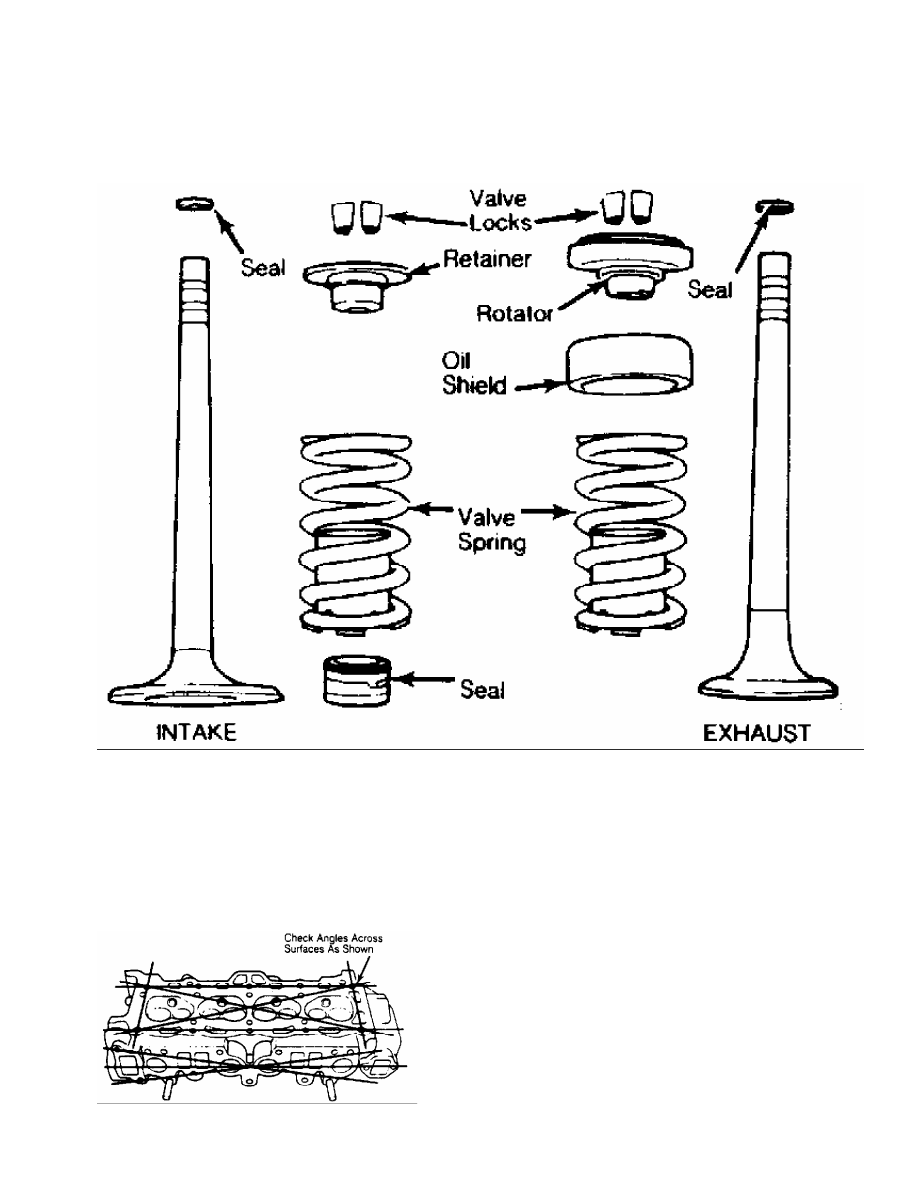
Fig. 2: Exploded View of Intake & Exhaust Valve Assemblies - Typical
This Graphic For General Information Only
CLEANING & INSPECTION
Clean cylinder head and valve components using approved
cleaning methods. Inspect cylinder head for cracks, damage or warped
gasket surface. Place straightedge across gasket surface. Determine
clearance at center of straightedge. Measure across both diagonals,
longitudinal centerline and across the head at several points. See
Fig. 3.
Fig. 3: Checking Cylinder Head for Warpage - Typical
This Graphic For General Information Only
On cast cylinder heads, if warpage exceeds .003" (.08 mm)
in a 6" span, or .006" (.15 mm) over total length, cylinder head must
be resurfaced. On most aluminum cylinder heads, if warpage exceeds .
002" (.05 mm) in any area, cylinder head must be resurfaced. Warpage
specification may vary with manufacturer.
Cylinder head thickness should be measured to determine
amount of material which can be removed before replacement is
required. Cylinder head thickness must not be less than manufacturer’s
specifications.
If cylinder head required resurfacing, it may not align
properly with intake manifold. On "V" type engines, misalignment is
corrected by machining intake manifold surface that contacts cylinder
head. Cylinder head may be machined on surface that contacts intake
manifold.
Using oil stone, remove burrs or scratches from all sealing
surfaces.
VALVE SPRINGS
Inspect valve springs for corroded or pitted valve spring
surfaces which may lead to breakage. Polished spring ends caused by
a rotating spring, indicates that spring surge has occurred. Replace
springs showing evidence of these conditions.
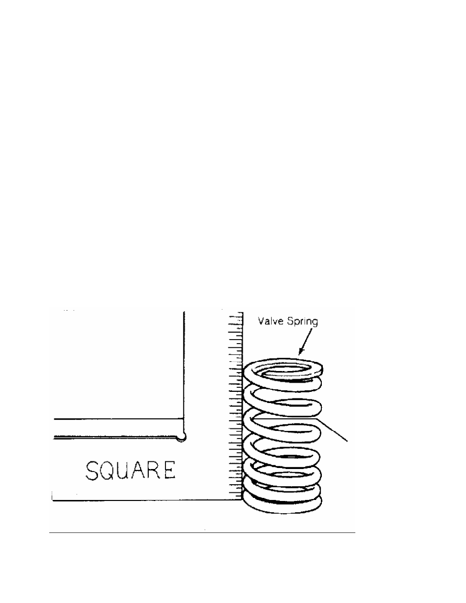
Inspect valve springs for squareness using a 90 degree
straightedge. See Fig. 4. Replace valve spring if out-of-square
exceeds manufacturer’s specification.
Fig. 4: Checking Valve Spring Squareness - Typical
This Graphic For General Information Only
Using vernier caliper, measure free length of all valve
springs. Replace springs if not within specification. Using valve
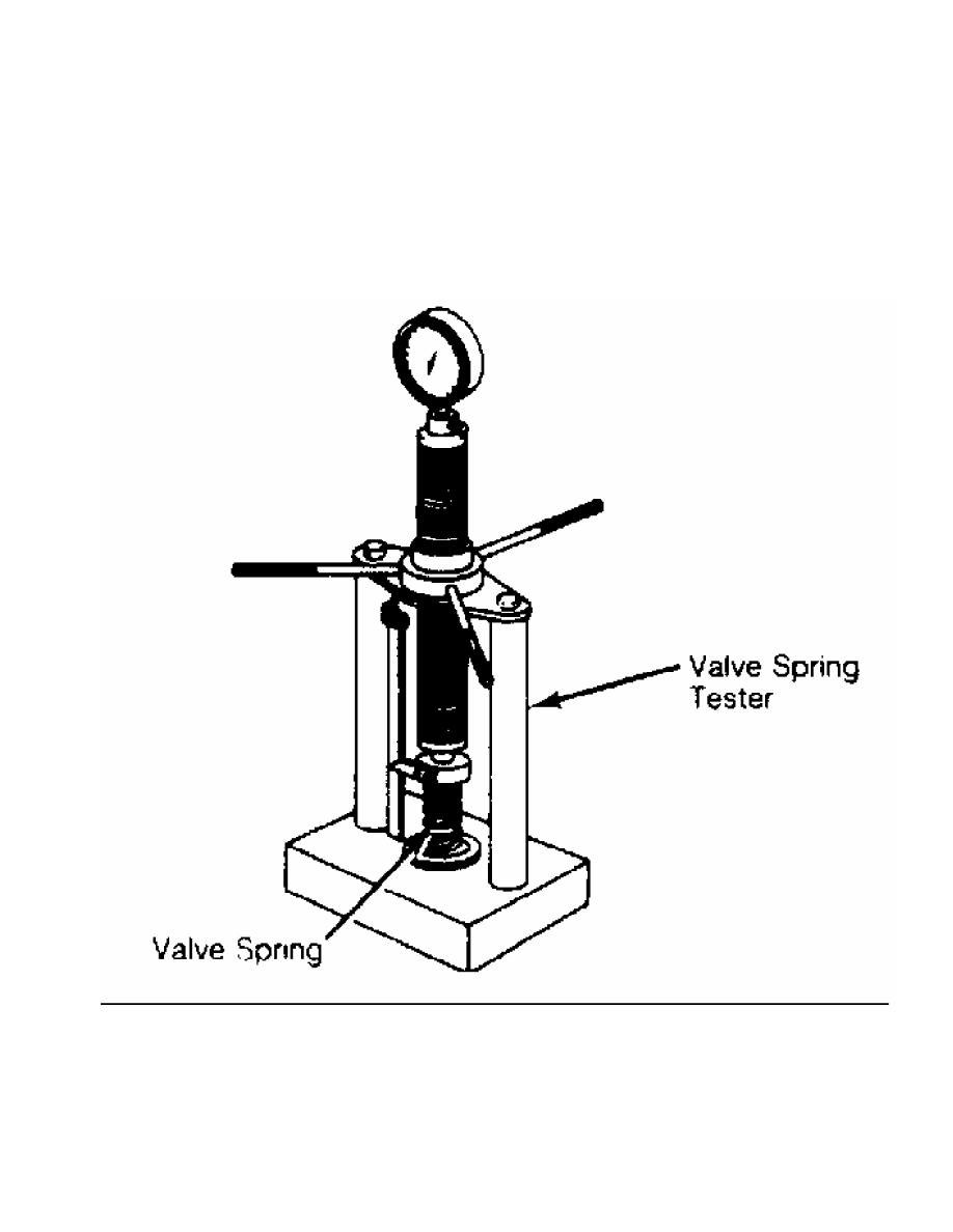
spring tester, test valve spring pressure at installed and compressed
heights. See Fig. 5.
Usually compressed height is installed height minus valve
lift. Replace valve spring if not within specification. It is
recommended to replace all valve springs when overhauling cylinder
head.
Fig. 5: Checking Valve Spring Pressure - Typical
This Graphic For General Information Only
VALVE GUIDE
Measuring Valve Guide Clearance
Check valve stem-to-guide clearance. Ensure valve stem
diameter is within specifications. Install valve in valve guide.
Install dial indicator assembly on cylinder head with tip resting
against valve stem just above valve guide. See Fig. 6.
Нет комментариевНе стесняйтесь поделиться с нами вашим ценным мнением.
Текст