Mitsubishi Montero (1991+). Manual — part 103
EMISSION CONTROL VISUAL INSPECTION PROCEDURES
1991 Mitsubishi Montero
1983-98 GENERAL INFORMATION
Emission Control Visual Inspection Procedures
All Models
* PLEASE READ THIS FIRST *
This article is provided for general information only. Not
all information applies to all makes and models. For more complete
information, see appropriate article(s) in the ENGINE PERFORMANCE
Section.
EMISSION CONTROL LABELS
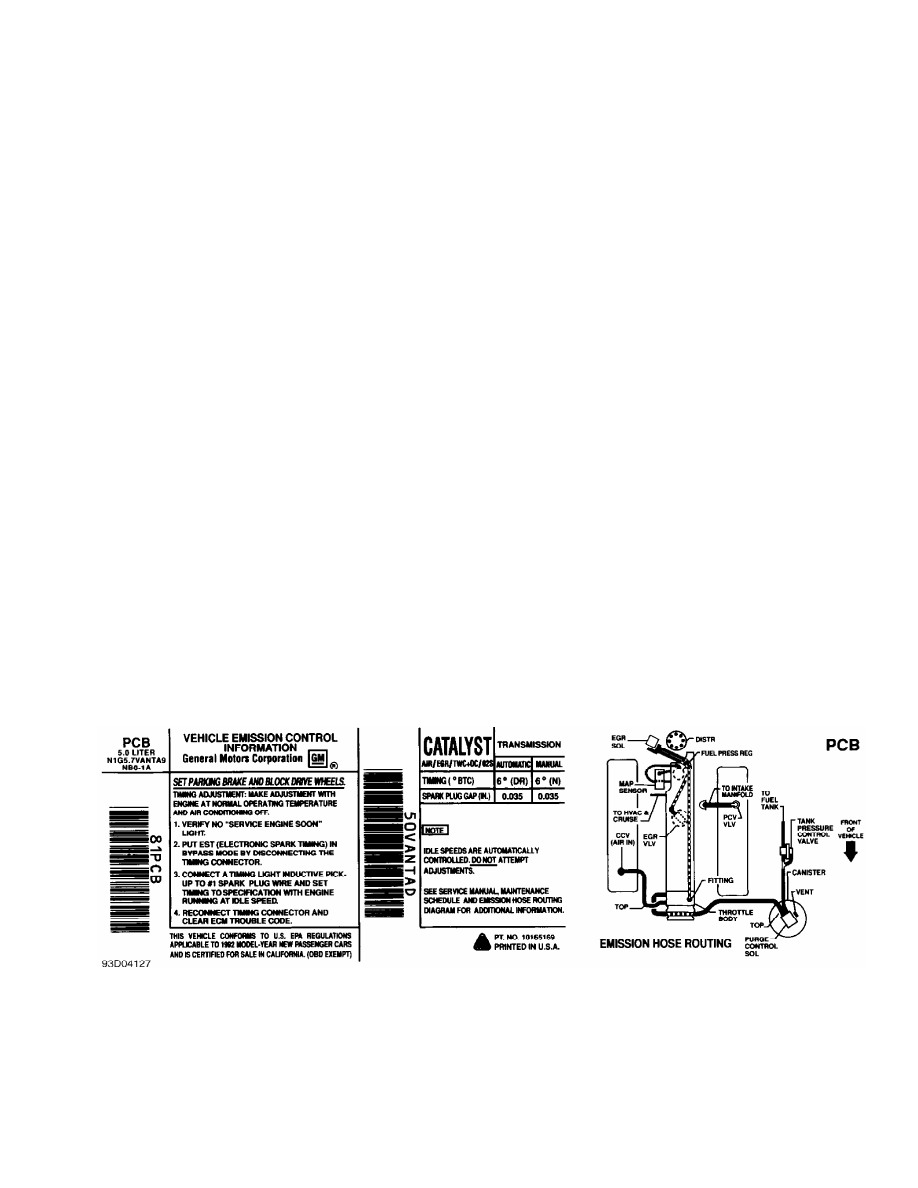
The vehicle manufacturer’s emission control label, also known
as the underhood tune-up label or Vehicle’s Underhood Emission Control
System (VECI) label, is located in the engine compartment. Information
regarding year model of vehicle, engine size, number of cylinders,
emission equipment or type, engine tune-up specifications, whether
vehicle was manufactured for sale in California or is a Federal
vehicle, vacuum hose routing schematic, etc., can be found on this
label. See Fig. 1.
In addition to the VECI label, some emission control
inspection and maintenance programs may require an additional label to
be affixed to the vehicle in special circumstances. For example, in
California, a Bureau Of Automotive Repair (BAR) engine label may be
affixed to the left door post. A BAR engine label is only used when
the vehicle has an engine change, approved modification or is a
Specially Constructed (SPCN) or an acceptable Gray market vehicle.
Check your state’s emission control inspection and maintenance laws to
determine if a similar label is used.
Fig. 1: Typical Emission Control Label
Courtesy of General Motors Corp.
EMISSION CONTROL VISUAL INSPECTION
* PLEASE READ THIS FIRST *
NOTE: The following emission control visual inspection procedures
should be used as a guide only. When performing a visual
inspection, always follow your state’s recommended
inspection procedures.
A visual inspection is made to determine if any required
emission control devices are missing, modified or disconnected.
Missing, modified or disconnected systems must be made fully
operational before a vehicle can be certified.
POSITIVE CRANKCASE VENTILATION (PCV)
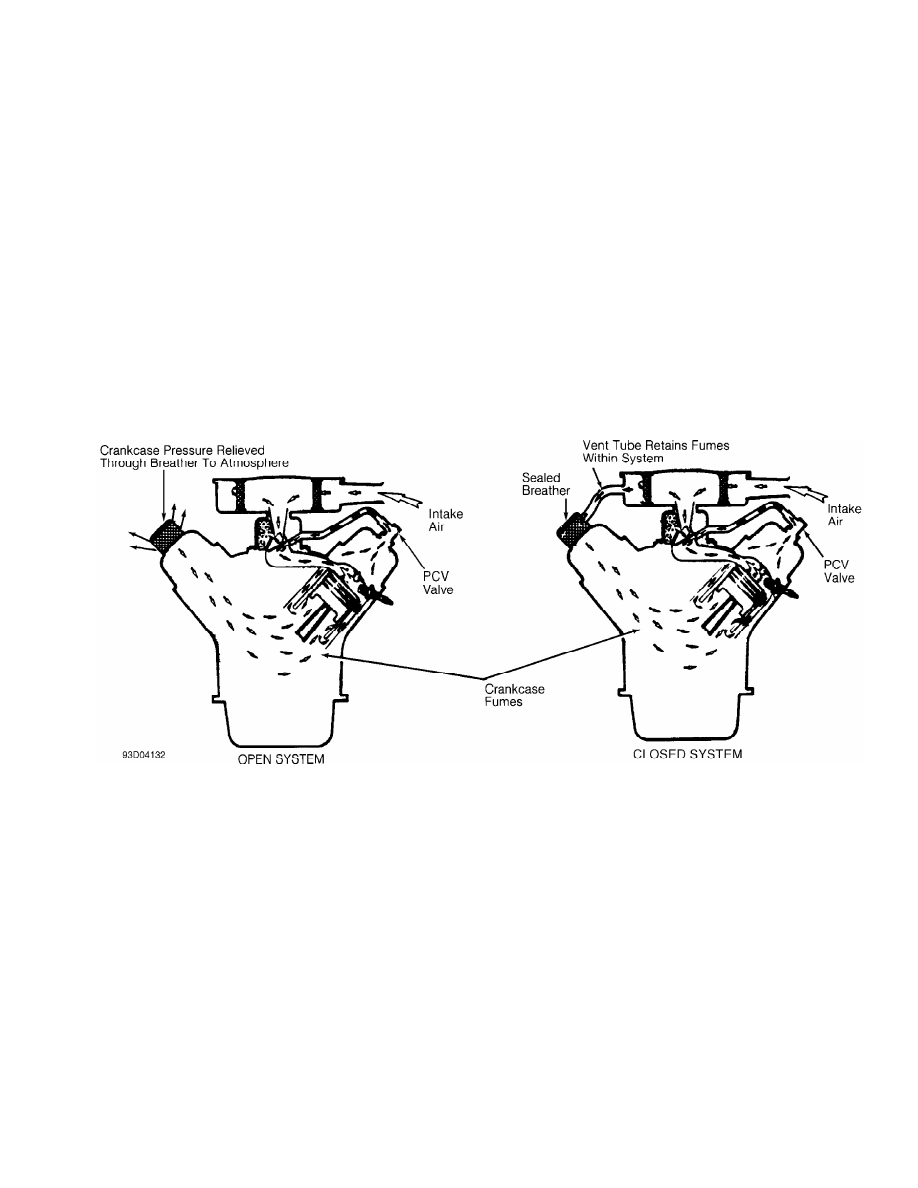
PCV controls the flow of crankcase fumes into the intake
manifold while preventing gases and flames from traveling in the
opposite direction. PCV is either an open or closed system. See Fig. 2
.
Ensure PCV system is installed as required. Verify valve,
required hoses, connections, flame arresters, etc., are present,
routed properly and in serviceable condition.
Fig. 2: Typical Open & Closed Type PCV System
THERMOSTATIC AIR CLEANER (TAC)
The TAC supplies warm air to air intake during cold engine
operation. This system is active during cold engine warm-up only.
Under all other operating conditions, air cleaner function is the same
as any non-thermostatic unit.
Ensure required exhaust shroud, hot air duct, vacuum hoses
and air cleaner components are present and installed properly. See
Fig. 3. Ensure any required thermostatic vacuum switches are in place
and vacuum hoses are installed and in serviceable condition. Also
ensure air cleaner lid is installed right side up. Check for oversized
air filter elements and for additional holes in the air cleaner
housing.
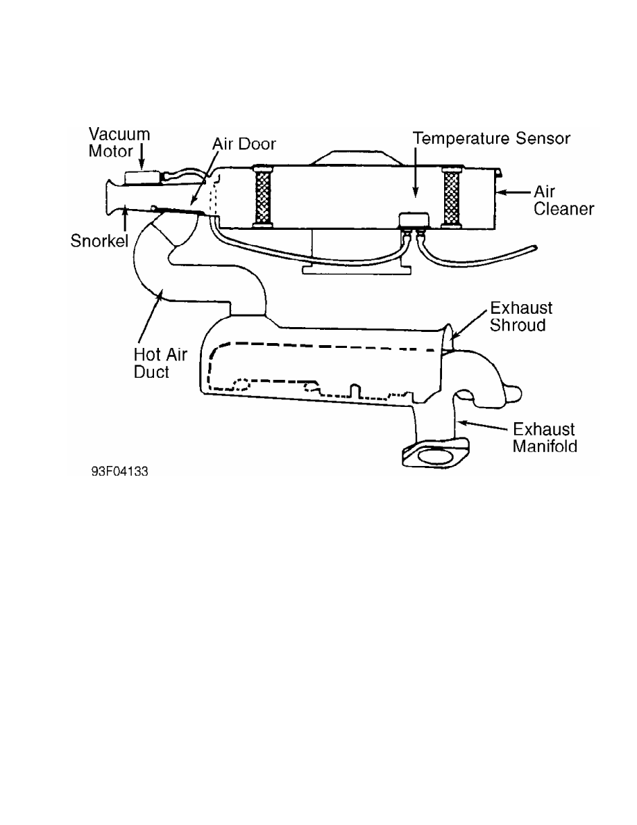
Fig. 3: Typical Thermostatic Air Cleaner System
FUEL EVAPORATIVE SYSTEM (EVAP)
The EVAP system allows for proper fuel system ventilation
while preventing fuel vapors from reaching the atmosphere. This means
that vapors must be caught and stored while the engine is off, which
is when most fuel evaporation occurs. When the engine is started,
these fuel vapors can be removed from storage and burned. In most
systems, storage is provided by an activated charcoal (or carbon)
canister. See Fig. 4. On a few early systems, charcoal canisters are
not used. Instead, fuel vapors are vented into the PCV system and
stored inside the crankcase.
The main components of a fuel evaporation system are a sealed
fuel tank, a liquid-vapor separator and vent lines to a vapor-storing
canister filled with activated charcoal. The filler cap is normally
not vented to the atmosphere, but is fitted with a valve to allow both
pressure and vacuum relief.
Although a few variations do exist between manufacturers,
basic operation is the same for all systems. Check for presence of
vapor storage canister or crankcase storage connections when required.
Ensure required hoses, solenoids, etc., are present and connected
properly. Check for proper type fuel tank cap. Check for any non-OEM
or auxiliary fuel tanks for compliance and the required number of
evaporation canisters.
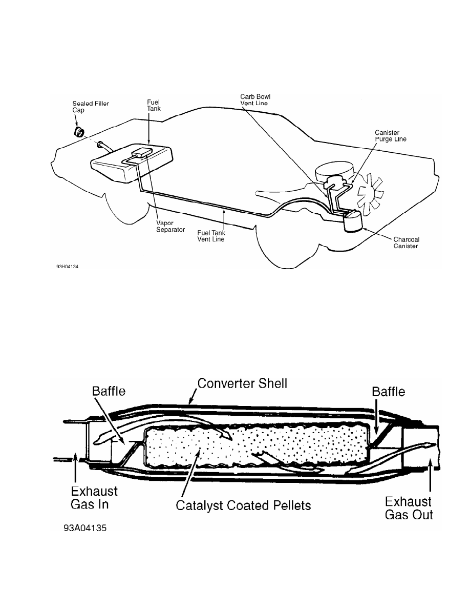
Fig. 4: Typical Fuel Evaporative System
CATALYTIC CONVERTERS
Oxidation Catalyst (OC)
This type of converter is the most common. It may use pellets
or monolith medium, depending upon application. See Fig. 5. Platinum
and palladium (or platinum alone) are used as catalyst in this type of
converter.
Visually check for presence of catalytic converter(s). Check
for external damage such as severe dents, removed or damaged heat
shields, etc. Also check for pellets or pieces of converter in the
tailpipe.
Fig. 5: Typical Oxidation Catalytic Converter (Pellet Type) Shown;
Typical Three-Way Catalytic Converter Is Similar
Courtesy of General Motors Corp.
Three-Way Catalyst (TWC)
This type of converter is nearly identical to a conventional
Нет комментариевНе стесняйтесь поделиться с нами вашим ценным мнением.
Текст