Mitsubishi Montero (1991+). Manual — part 165
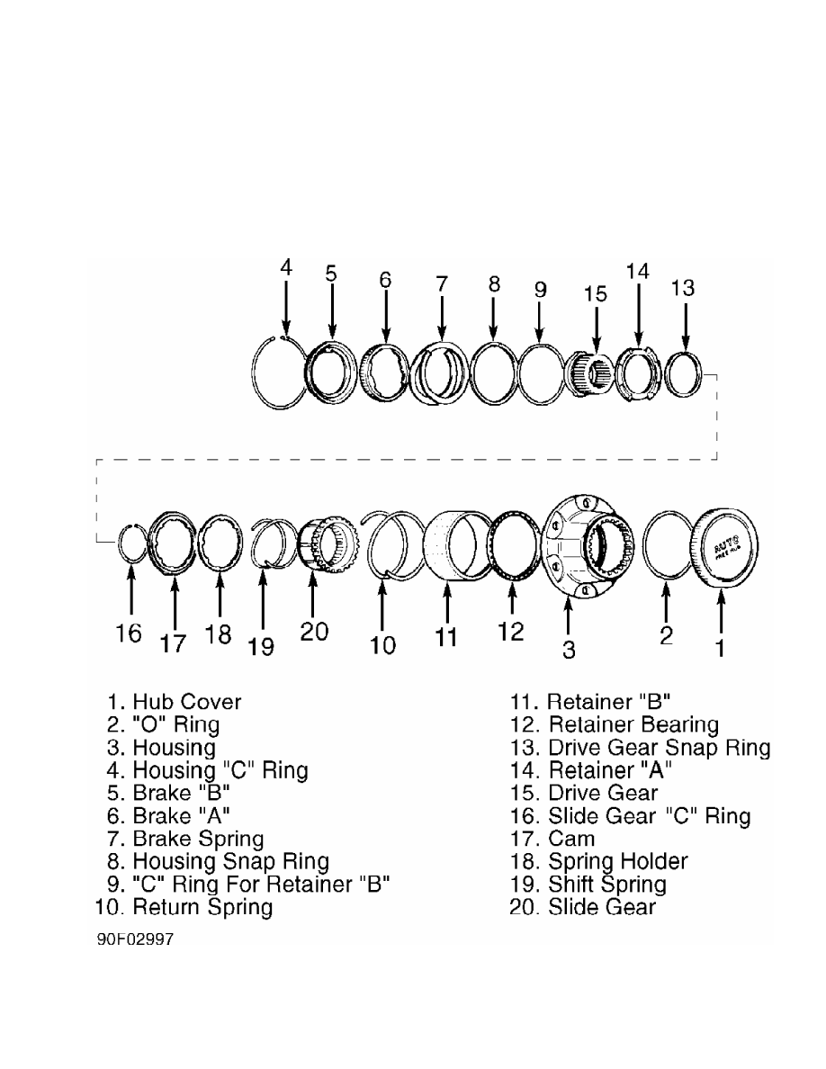
1) Remove locking hub. See REMOVAL & INSTALLATION. Push brake
"B" in hub housing and remove housing "C" ring. See Fig. 1. Using
Adapter (MB990811-01), lightly press drive gear assembly and remove
"C" ring from retainer "B". Slowly release drive gear assembly.
2) Remove drive gear assembly, slide gear assembly and return
spring. Remove slide gear "C" ring. Remove shift spring.
Fig. 1: Exploded View of Locking Hub
Courtesy of Chrysler Motors.
INSPECTION
1) Check drive gear and slide gear splines for damage. Check
cam portion of retainer "A" for wear or damage. Check cam for wear and
damage. Check slide gear and housing tooth surfaces for damage. Check
retainer "B" and housing contact surfaces for wear and damage.
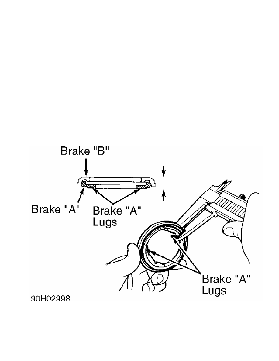
2) Check brake assembly thickness. See Fig. 2. Assemble brake
"A" and brake "B". Using slide calipers, measure thickness of
assembled brake at both brake "A" lugs.
3) Standard thickness is .413" (10.49 mm). Minimum thickness
is .378" (9.60 mm). If measured thickness is less than minimum
thickness, replace brake "A" and brake "B".
4) Check length of return spring. Measure length "A" of
spring. Ensure length "A" is 1.38" (35.1 mm). See Fig. 3. If length
"A" is NOT as specified, replace return spring.
5) Check length of shift spring. Measure length "B" of
spring. Ensure length "B" is 1.18" (30.0 mm). See Fig. 3. If length
"B" is NOT as specified, replace shift spring.
Reassembly Pack grooves of retainer "B" with multipurpose
grease and apply grease to attaching surfaces of all components. To
complete assembly, reverse disassembly procedure.
Fig. 2: Measuring Brake Assembly Thickness
Courtesy of Chrysler Motors.
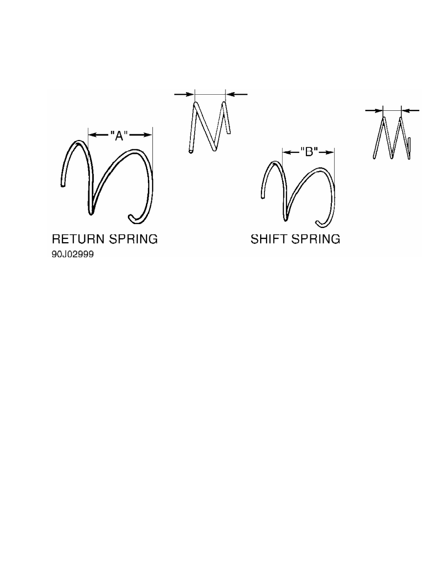
Fig. 3: Measuring Lengths of Return Spring & Shift Spring
Courtesy of Chrysler Motors.
TORQUE SPECIFICATIONS
TORQUE SPECIFICATIONS
Application Ft. Lbs. (N.m)
Hub Cover . . . . . . ... 13-25 (18-34)
Locking Hub Bolts . . . . ... 36-43 (49-58)
MAINTENANCE INFORMATION
1991 Mitsubishi Montero
1983-96 MAINTENANCE
Mitsubishi Maintenance Information
Montero
* PLEASE READ THIS FIRST *
NOTE: For scheduled maintenance intervals and the related fluid
capacities, fluid specifications and labor times for major
service intervals, see SCHEDULED SERVICES article below:
* SCHEDULED SERVICES - 1983-86
* SCHEDULED SERVICES - 1987-95
* SCHEDULED SERVICES - 1996
Warranty information and specifications for fluid
capacities, lubrication specifications, wheel and tire size,
and battery type are covered in this article.
MODEL IDENTIFICATION
VIN LOCATION
The Vehicle Identification Number (VIN) is located on the
left side of the dash panel at the base of the windshield. The VIN
chart explains the code characters.
VIN CODE ID EXPLANATION
Numbers preceding the explanations in the legend below refer
to the sequence of characters as listed on VIN identification label.
See VIN example below.
(VIN) J A 4 F J 4 3 E 1 H J 0 0 0 0 0 1
1 2 3 4 5 6 7 8 9 10 11 12 13 14 15 16 17
1 - Manufacturing Country
J * Japan
2 - Manufacturer
A * Mitsubishi Motor Corp.
3 - Vehicle Type
4 * Multi-Purpose Vehicle
7 * Truck
4 - GVW & Brake Type
F * 4001-5000 Lbs., Hydraulic Brakes
G * 5001-6000 Lbs., Hydraulic Brakes
5 - Vehicle Line
J, K Or R * Montero
6 - Vehicle Series
2 * Low
3 * Medium
Нет комментариевНе стесняйтесь поделиться с нами вашим ценным мнением.
Текст