Mitsubishi Montero (1991+). Manual — part 66
INNER SHAFT SPECIFICATIONS
Application In. (mm)
Shaft O.D.
Bearing Area . . . . 1.38 (35.0)
Center Area . . . . . 1.24 (31.4)
INSTALLATION
1) If oil seal replacement is necessary, install new oil seal
in differential carrier using Oil Seal Installer (MB990934-01) and
Handle (MB990938-01). Coat seal lips with grease. Install housing
tube. Using Seal Installer (MB990955) and Handle (C-4171), install new
dust seal in housing tube. Dust seal must be even with housing tube.
Coat seal lip with grease.
2) Using a pipe with O.D. of 2.95" (74.3 mm), wall thickness
of .16" (4.0 mm) and with overall length of 1.97" (50.0 mm), install
dust cover on shaft. Coat inside of dust cover with grease. Press
bearing on shaft. Install new circlip on inner shaft. Drive inner
shaft into differential. Use care not to damage oil seal.
DRIVE AXLES & BEARINGS OVERHAUL
NOTE: References to BJ refer to Birfield Joint and DOJ to Double
Offset Joint.
DISASSEMBLY
1) Remove boot bands. Remove circlip from DOJ outer race.
Separate drive axle from DOJ outer race. Remove balls from DOJ cage.
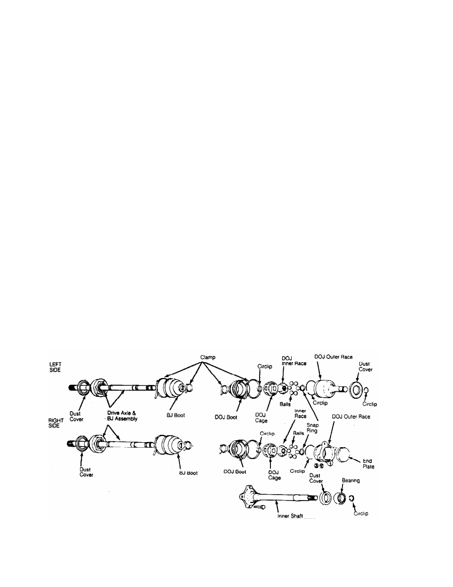
Remove DOJ cage from DOJ inner race in direction of BJ. See Fig. 2.
Fig. 2: Exploded View of Drive Axles
Courtesy of Chrysler Motors.
2) Remove snap ring from drive axle shaft. Remove DOJ inner
race from shaft. Remove circlip from shaft. Wrap tape around splines
of shaft to prevent boot damage during removal.
3) Remove DOJ boot. Note size of boot. Remove dust cover from
shaft. Straighten BJ boot protector and remove protector band. Move
boot protector toward BJ side of shaft and remove. Remove BJ boot.
CAUTION: Drive axle and BJ are serviced as a unit. DO NOT
disassemble BJ and drive axle.
REASSEMBLY
1) Coat shaft with light coat of grease. Wrap splines with
tape. Install BJ boot, bands and DOJ boot on shaft. Ensure correct
size boot is installed in proper location.
2) Boot bands must be installed so lever is pulled toward
rear of vehicle when band is tightened. Pack proper amount of grease
in BJ and BJ boot. See GREASE APPLICATION table.
3) Place DOJ cage on shaft with smaller diameter installed
first. Install circlip, DOJ inner race, and snap ring on shaft. Apply
grease to DOJ inner race and cage. Install balls into cage.
4) Apply proper amount of grease to outer DOJ race. Install
shaft into DOJ outer race. Apply proper amount of grease to DOJ outer
race and install circlip. See GREASE APPLICATION table.
5) Place DOJ boot over DOJ outer race. Install boot bands so
lever is pulled toward rear of vehicle when band is tightened. Adjust
DOJ boot bands to have proper distance between centerline of boot
bands. See BOOT BAND SPECIFICATIONS table. This distance is necessary
to control air in DOJ boot. Tighten boot bands.
6) Install boot protector and band. Install dust cover on
shaft. Use a pipe with O.D. of 2.68" (68.0 mm), wall thickness of .09"
(2.3 mm) and with overall length of 6.70" (170.1 mm) to install dust
cover.
GREASE APPLICATION
Application Ozs. (g)
BJ Boot
Montero
3.0L Engine . . . . .. 4.6 (130)
All Others . . . . . 3.9 (110)
DOJ Outer Race
Montero
3.0L Engine . . . . ... 2.3 (60)
All Others . . . . . . 1.9 (55)
BOOT BAND SPECIFICATIONS
Application In. (mm)
All Models . . .. 3.03-3.27 (76.9-83.0)
DIFFERENTIAL DISASSEMBLY
1) Remove differential carrier from vehicle. See DIFFERENTIAL
CARRIER R & I in this article. Remove cover. Mark bearing caps for
reassembly reference. Remove bearing caps. Remove differential case
assembly from carrier.
CAUTION: Ensure adjusting spacers, bearing caps, gears and side
bearings are marked for reassembly reference. Components
must be installed in original location.
2) Using bearing puller, remove differential case side
bearings. Loosen ring gear retaining bolts in diagonal sequence.
Remove ring gear.
3) Remove drive pinion shaft lock pin from ring gear side.
Remove pinion shaft and pinion gears. Remove side gears and thrust
spacers.
DRIVE PINION
1) Remove pinion flange nut. Scribe alignment mark on pinion
flange and pinion. Remove flange. Using soft-faced hammer, drive out
pinion. Remove rear bearing and oil seal from carrier. Remove rear
adjusting shim from pinion.
2) Press front bearing from pinion. Remove front adjusting
shim and spacer from pinion. Inspect all components for unusual wear
or damage. Replace as necessary.
DIFFERENTIAL REASSEMBLY & ADJUSTMENTS
CASE REASSEMBLY
1) Place side gear thrust spacers behind side gears in
original position. Assemble side gears in differential case. Install
pinion gears and washers. Rotate pinion gears to mesh with side gears.
2) Install pinion shaft without lock pin. Check pinion and
side gear backlash. Install wooden wedge to lock side gears. Using
dial indicator, measure gear backlash. See Fig. 3.
3) Backlash must be within specification. See PINION & SIDE
GEAR BACKLASH SPECIFICATIONS table. Adjust backlash by using different
side gear spacers. Ensure both sides are equally shimmed.
4) Install pinion shaft lock pin. Securely stake in 2 places.
Ensure adhesive is removed from ring gear mounting bolts and gear
mounting surface. Clean internal threads with tap.
5) Install ring gear on differential case. Ensure alignment
marks on differential case and ring gear are aligned. Apply Loctite
271 to bolts and install. Tighten bolts alternately in diagonal
sequence to specification. See TORQUE SPECIFICATIONS table at the end
of this article.
PINION & SIDE GEAR BACKLASH SPECIFICATIONS
Application In. (mm)
Standard . . . . . ... .003 (.08)
Wear Limit . . . . . . .008 (.20)
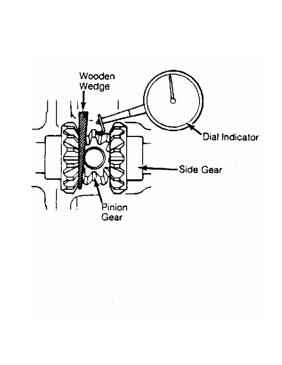
Fig. 3: Checking Pinion & Side Gear Backlash
Courtesy of Chrysler Motors.
DRIVE PINION DEPTH
Нет комментариевНе стесняйтесь поделиться с нами вашим ценным мнением.
Текст