Mitsubishi Montero (1991+). Manual — part 41
ANTI-LOCK BRAKE SAFETY PRECAUTIONS
1991 Mitsubishi Montero
GENERAL INFORMATION
Anti-Lock Brake Safety Precautions
* PLEASE READ THIS FIRST *
This article is intended for general information purposes
only. This information may not apply to all makes and models. If
vehicle is equipped with Anti-Lock Brake System (ABS), refer to
appropriate ANTI-LOCK BRAKE SYSTEM article in the BRAKES section for
description, operation, depressurizing, testing, system bleeding,
trouble shooting and servicing of specific system.
WARNING: Failure to depressurize ABS could lead to physical injury.
ANTI-LOCK BRAKE SAFETY PRECAUTIONS
WARNING: Failure to depressurize ABS could lead to physical injury.
* NEVER open a bleeder valve or loosen a hydraulic line
while ABS is pressurized.
* NEVER disconnect or reconnect any electrical connectors
while ignition is on. Damage to ABS control unit may result.
* DO NOT attempt to bleed hyudarulic system without first
referring to the appropriate ANTI-LOCK BRAKE SYSTEM article
in the BRAKES section.
* Only use specially designed brake hoses/lines on ABS equipped
vehicles.
* DO NOT tap on speed sensor components (sensor, sensor rings).
Sensor rings must be pressed into hubs, NOT hammered into
hubs. Striking these components can cause demagnetization or
a loss of polarization, affecting the accuracy of the speed
signal returning to the ABS control unit.
* DO NOT mix tire sizes. Increasing the width, as long as tires
remain close to the original diameter, is acceptable. Rolling
diameter must be identical for all 4 tires. Some
manufacturers recommend tires of the same brand, style and
type. Failure to follow this precaution may cause inaccurate
wheel speed readings.
* DO NOT contaminate speed sensor components with grease. Only
use recommended coating, when system calls for an
anti-corrosion coating.
* When speed sensor components have been removed, ALWAYS check
sensor-to-ring air gaps when applicable. These specifications
can be found in each appropriate article.
* ONLY use rocommended brake fluids. DO NOT use silicone brake
fluids in an ABS equipped vehicle.
* When instlling transmittion devices (CB’s, telephones, etc.)
on ABS equipped vehicles, DO NOT locate the antenna near the
ABS control unit (or any control unit).
* Disconnect all on-board computers, when using electric
welding equipment.
* DO NOT expose the ABS control unit to prolonged periods of
high heat (185 F/85 C for 2 hours is generally considered a
maximum limit).
F - BASIC TESTING
1991 Mitsubishi Montero
1991 ENGINE PERFORMANCE
Basic Diagnostic Procedures
Chrysler; Colt, Colt 200, Colt Vista, Ram-50, Stealth,
Summit
Mitsubishi; Eclipse, Galant, Mirage, Montero, Pickup, 3000GT
INTRODUCTION
The following diagnostic steps will help prevent overlooking
a simple problem. This is also where to begin diagnosis for a no start
condition. First step in diagnosing any driveability problem is
verifying customer’s complaint with a test drive under conditions
problem reportedly occurred.
Before entering self-diagnostics, perform a careful and
complete visual inspection. Most engine control problems result from
mechanical breakdowns, poor electrical connections or
damaged/misrouted vacuum hoses. Before condemning computerized system,
perform each test listed in article.
NOTE: Perform all voltage tests with a Digital Volt-Ohmmeter (DVOM)
with a minimum 10-megohm input impedance, unless stated
otherwise in test procedure.
PRELIMINARY INSPECTION & ADJUSTMENTS
VISUAL INSPECTION
Visually inspect all electrical wiring, looking for chafed,
stretched, cut or pinched wiring. Ensure electrical connectors fit
tightly and are not corroded. Ensure distributor cap and rotor are
free of cracks, carbon trails or contamination. Ensure vacuum hoses
are properly routed and not pinched or cut. See M - VACUUM DIAGRAMS
article in the ENGINE PERFORMANCE Section to verify routing and
connections (if necessary). Inspect air induction system for possible
vacuum leaks.
MECHANICAL INSPECTION
Compression
Check engine mechanical condition with a compression gauge,
vacuum gauge, or an engine analyzer. See engine analyzer manual for
specific instructions.
WARNING: DO NOT use ignition switch during compression tests. Use a
remote starter to crank engine. Fuel injectors on many models
are triggered by ignition switch during cranking mode, which
can create a fire hazard or contaminate engine’s oiling
system.
COMPRESSION SPECIFICATIONS TABLE (1)
Application Specification
psi (kg/cm
)
1.5L (VIN X) . . . . . . . .. 137 (9.6)
1.6L (VIN Y) . . . . . . . . 171 (12.0)
1.8L (VIN T) . . . . . . . .. 131 (9.2)
2.0L (VIN R) DOHC . . . . . . . 137 (9.6)
2.0L (VIN U) DOHC Turbo . . . . ... 114 (8.0)
2.0L (VIN V) SOHC . . . . . . . 119 (8.4)
2.4L (VIN W) SOHC . . . . . . . 119 (8.4)
3.0L (VIN S) SOHC . . . . . . . 119 (8.4)
3.0L (VIN B) DOHC . . . . . . . 139 (9.8)
3.0L (VIN C) DOHC Turbo . . . . ... 115 (8.1)
(1) - Maximum variation between cylinders 14 psi
(1.0 kg/cm
)
Exhaust System Backpressure
Exhaust system can be checked with a vacuum or pressure
gauge. Remove O2 sensor or air injection check valve (if equipped).
Connect a 1-10 psi pressure gauge and run engine at 2500 RPM. If
exhaust system backpressure is greater than 1 3/4-2 psi, exhaust
system or catalytic converter is plugged. If a vacuum gauge is used,
connect vacuum gauge hose to intake manifold vacuum port and start
engine. Observe vacuum gauge. Open throttle part way and hold steady.
If vacuum gauge reading slowly drops after stabilizing, exhaust system
should be checked for a restriction.
FUEL PRESSURE
Basic diagnosis of fuel system should begin with determining
fuel system pressure.
FUEL INJECTED ENGINES
WARNING: ALWAYS relieve fuel pressure before disconnecting any fuel
injection-related component. DO NOT allow fuel to contact
engine or electrical components.
Fuel Pressure
1) On all models except Colt and Mirage, disconnect fuel pump
harness connector at fuel tank. On Colt and Mirage, remove rear seat
cushion to disconnect fuel pump harness connector.
2) On all models, start engine. Let engine run until it
stops. Turn ignition off. Disconnect negative battery terminal.
Connect fuel pump harness connector.
WARNING: Before disconnecting high pressure fuel hose at fuel delivery
pipe, cover fuel hose connection with a rag. Some residual
fuel pressure may still be in system.
3) On Galant 2.0L (DOHC), remove brace for access to high
pressure fuel delivery pipe. On all engines, disconnect high pressure
fuel hose at fuel delivery pipe.
4) Connect fuel pressure gauge with adapter between fuel
delivery pipe and high pressure hose. See Fig. 1. Connect negative
battery terminal. Connect battery voltage to fuel pump test terminal.
See FUEL PUMP TEST TERMINAL LOCATION table. Ensure no fuel leaks are
present. Disconnect battery voltage to fuel pump test terminal.
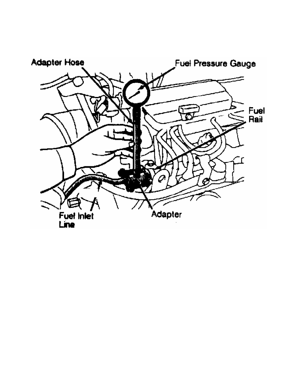
Fig. 1: Fuel Pressure Testing Connection ID (Typical Fuel Inj. Eng.)
Courtesy of Mitsubishi Motor Sales of America.
5) Start engine and let idle. Measure fuel pressure with
vacuum hose connected to fuel pressure regulator. Record fuel pressure
reading. Disconnect and plug vacuum hose from fuel pressure regulator.
Record fuel pressure reading. See REGULATED FUEL PRESSURE table.
6) Check for fuel pressure in fuel return hose by gently
pinching hose while increasing engine speed. If fuel volume is low,
fuel pressure in return hose will not be felt. Increase engine speed
to 2500-3000 RPM, 2-3 times. Return engine to idle. Fuel pressure
should not drop when engine is returned to idle.
7) Turn engine off. Ensure fuel pressure reading does not
decrease within 2 minutes. If a decrease is noted, monitor speed of
decrease.
8) If fuel pressure is lower than specification, fuel
pressure drops at idle after increasing engine speed to 2500-3000 RPM,
or no fuel pressure in fuel return hose can be felt, check for clogged
fuel filter, faulty fuel pressure regulator, or fuel pump.
9) If fuel pressure is higher than specification, check for a
faulty fuel pressure regulator or plugged fuel return line. If fuel
pressure does not change when vacuum hose to regulator is connected or
disconnected, check for a leaking or clogged vacuum hose to fuel
pressure regulator or faulty fuel pressure regulator.
10) If fuel pressure decreases suddenly after engine is
stopped, check valve within fuel pump is not seated. Replace fuel
Нет комментариевНе стесняйтесь поделиться с нами вашим ценным мнением.
Текст