Mitsubishi Montero (1991+). Manual — part 152
With lever set at OUTSIDE position, outside air is allowed to enter
and/or pass through heater. With lever set at INSIDE position, air is
recirculated inside passenger compartment.
BLOWER SWITCH
The blower can be operated at different fan speeds to
regulate amount of air forced through vehicle. Fan speed will increase
as switch is turned or moved right.
AIR CONTROL INDICATION SYSTEM
This system consists of indication lights built into
instrument cluster and 4 switches connected to various control levers.
An indication light glows when heater blower is on. Lights also
indicate choice of outlets and whether air source is inside or outside
vehicle. In addition, temperature of air directed from outlets is
indicated for each air outlet by light colors of green (cool air) and
orange (warm air).
ADJUSTMENTS
HEATER (TEMPERATURE) CONTROL VALVE
Place control lever to indicated position. See TEMPERATURE
CONTROL CABLE ADJUSTMENT table. See Fig. 3. Connect cable to heater
control valve and/or air damper lever according to table. Secure cable
sleeve using clips. With engine running, check for coolant leaks and
check operation of heater control valve. If heater control valve does
not operate properly, adjust by moving cable sleeve forward or
backward at retaining clip.
TEMPERATURE CONTROL CABLE ADJUSTMENT TABLE
Application Control Lever Water Valve
Position Lever Position
Montero . . . . . Far Left . . . ... Toward cable
Pickup & Ram-50 . . . Far Left . . (2) Away from cable
(2) - Disconnect link between air damper lever and water valve
lever. Close water valve. Close air damper. Reconnect link.
Attach cable to clip.
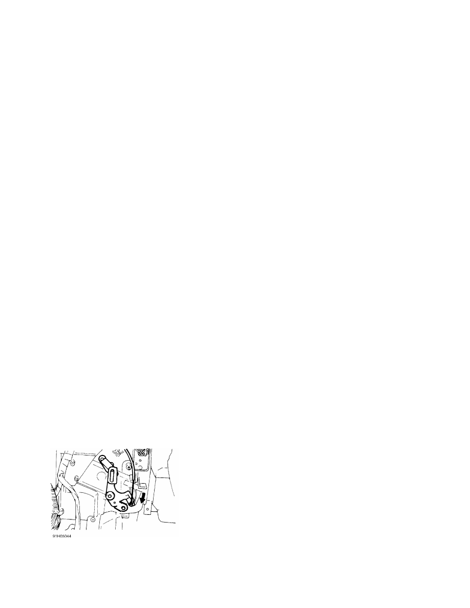
Fig. 3: Adjusting Temperature Control Cable (Typical)
Courtesy of Mitsubishi Motor Sales of America.
INSIDE/OUTSIDE AIR SELECTION CABLE
Move control lever to INSIDE position. Connect cable to
damper lever with outside air intake to heater closed. Apply
multipurpose grease to rotating portions of sliding lever. Check for
proper damper operation by moving control lever. To adjust, press air
control lever toward cable and move outer wire at retaining clip. See
Fig. 4.
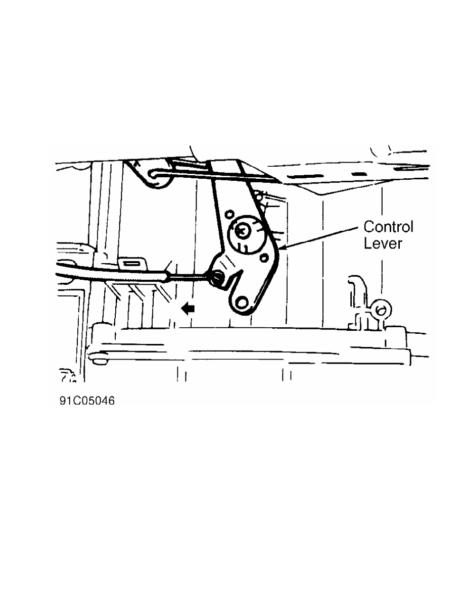
Fig. 4: Adjusting Air Selection Cable (Typical)
Courtesy of Mitsubishi Motor Sales of America.
MODE SELECTOR LEVER
Place selection lever in DEF position, and remove cable clip.
Ensure defroster door is fully open. Secure cable sleeve using clips.
Move lever to other positions to check for correct operation. Adjust
cable, if necessary, by moving sleeve forward or backward at retaining
clip.
TROUBLE SHOOTING
BLOWER MOTOR INOPERATIVE
Blown blower fuse. Blower motor improperly grounded.
Defective switch or faulty blower motor wiring connections. Foreign
object in fan.
INSUFFICIENT HEAT
Incorrect thermostat in cooling system. Improperly adjusted
temperature control cable. Clogged heater core fins. Faulty heater
control valve.
NO TEMPERATURE REGULATION
Clogged or stuck heater control valve. Incorrect installation
of heater control valve control cable. Incorrect adjustment of heater
control valve link.
NO VENTILATION
Incorrect adjustment of change-over dampers. Duct connection
loose.
TESTING
BLOWER MOTOR SWITCH TEST
Blower motor switch can be tested using an ohmmeter. Insert
test leads into appropriate connector terminals, and check continuity.
See BLOWER SWITCH CONTINUITY table. See Fig. 5 or 6.
BLOWER MOTOR SWITCH CONTINUITY TABLE
Continuity Between
Switch Position Terminal Nos.
Montero
Low . . . . . . . . 1-2 & 1-7
Medium 1 . . . . . . ... 2-4 & 4-7
Medium 2 . . . . . . ... 2-5 & 5-7
High . . . . . . . ... 2-6 & 6-7
1992 Montero
Low . . . . . . . . 1-8 & 3-5
Medium 1 . . . . . . ... 1-8 & 5-6
Medium 2 . . . . . .. 1-4, 1-8 & 2-5
High . . . . . . .. 1-4, 1-8 & 5-7
Pickup & Ram-50
Low . . . . . . ... 1-2, 2-6 & 7-8
Medium 1 . . . . . .. 1-3, 3-6 & 7-8
Medium 2 . . . . . .. 1-4, 4-6 & 7-8
High . . . . . . .. 1-5, 5-6 & 7-8
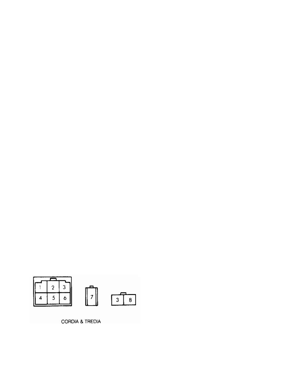
Fig. 5: Blower Motor Switch Connector Terminal ID (Pickup & Ram-50)
Courtesy of Mitsubishi Motor Sales of America.
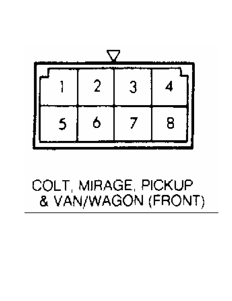
Fig. 6: Blower Motor Switch Connector Terminal ID (Montero)
Courtesy of Mitsubishi Motor Sales of America.
BLOWER MOTOR TEST
1) Turn ignition on. Check fuses. If fuses are bad, check
wiring harness for short circuits. If fuses are okay, check voltage
between heater relay and ground circuit. If voltage does not exist at
heater relay, check for broken wire between fuse block and heater
relay.
2) If voltage exists at heater relay, check relay, and
replace if necessary. See BLOWER MOTOR RELAY TEST under TESTING. If
relay is okay, disconnect blower motor connector. Set heater switch to
either LO, MED or HI setting.
3) Check voltage between harness side of connector and
vehicle ground. Battery voltage should be present. If battery voltage
is present, go to next step. If battery voltage is not present, check
continuity between resistor terminals. See BLOWER MOTOR RESISTOR TEST
under TESTING. If continuity is not present, replace resistor.
Нет комментариевНе стесняйтесь поделиться с нами вашим ценным мнением.
Текст