Mitsubishi Montero (1991+). Manual — part 174
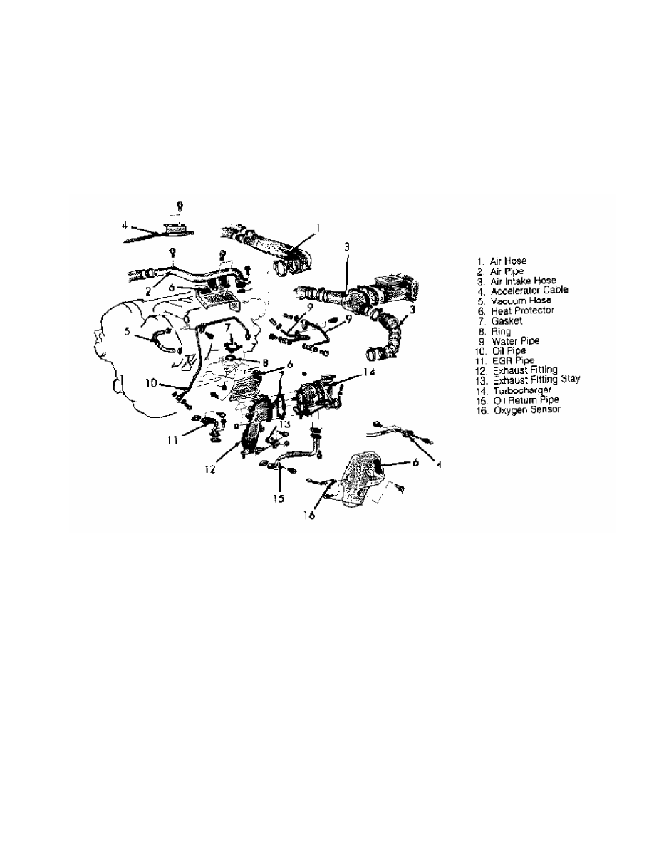
intake hoses and EGR pipe. Disconnect oxygen sensor electrical
connector.
2) Remove oil pipe and EGR valve. Disconnect exhaust fitting
and remove rear heat protector. Remove oil return pipe. Remove
turbocharger assembly. See Fig. 11.
Fig. 11: Removing Rear Turbocharger (Stealth & 3000GT)
Courtesy of Mitsubishi Motor Sales of America.
Inspection
Check turbine and compressor wheels for cracking and other
damage. Make sure turbine and compressor wheels turn smoothly. Check
for oil leakage from turbocharger assembly. Check for proper wastegate
valve operation. See SYSTEM & COMPONENT TESTING article.
Installation
1) To install, reverse removal procedure. Before oil pipe
flare nut (above turbocharger) is installed, pour clean engine oil
into turbocharger. Ensure oil and air hoses are properly installed and
securely clamped.
2) Use new gaskets. Adjust accelerator cable (if necessary).
Refill engine oil and coolant. Check for oil and coolant leaks.
Tighten all bolts to specification. See TORQUE SPECIFICATIONS table.
TORQUE SPECIFICATIONS
TORQUE SPECIFICATIONS TABLE
Applications Ft. Lbs. (N.m)
Fuel Tank Nuts . . . . . . . . 15-22 (20-30)
Fuel Tank Drain Plug . . . . . ... 11-18 (15-24)
Exhaust Manifold-To-Engine Nuts . . . 18-22 (24-30)
Exhaust Manifold-To-Turbocharger Bolts . . 40-47 (54-64)
Exhaust Pipe Bolts . . . . . . . 22-29 (30-39)
Oil Pipe-To-Engine . . . . . . . 10-14 (14-19)
Oxygen (O2) Sensor . . . . . . . 29-36 (39-49)
Plenum-To-Intake Manifold Bolts . . . 11-15 (15-20)
Water Pipe-To-Turbocharger
Except Stealth & 3000GT . . . . .. 25-36 (34-49)
Stealth & 3000GT . . . . . . . ... 22 (30)
INCH Lbs. (N.m)
Fuel Rail Bolts . . . . . . .. 84-108 (10-12)
Heat Protector Bolts . . . . . . 108-132 (12-15)
ISC Switch Screws . . . . . . 20-54 (2.5-4.5)
TPS Switch Screws . . . . . . 13-20 (1.5-2.5)
Wastegate Actuator Bolts . . . . ... 84-108 (9-12)
RIDING HEIGHT ADJUSTMENT
1991 Mitsubishi Montero
1991-92 WHEEL ALIGNMENT
Riding Height Adjustment
Chrysler Motors: Ram-50
Mitsubishi: Montero, Pickup
RIDING HEIGHT ADJUSTMENT
Before adjusting alignment, check riding height. Ensure
vehicle is on level floor and tires are properly inflated. Bounce
vehicle several times and allow suspension to settle.
Visually inspect vehicle, from front to rear or side to
side, for signs of abnormal height. Remove extra heavy items from
passenger and luggage compartments. If riding height is not within
specification, check and repair suspension before adjusting alignment.
See RIDING HEIGHT SPECIFICATIONS (FRONT) table.
RIDING HEIGHT SPECIFICATIONS (FRONT) (1)
Application (2) In. (mm)
Montero . . . . . . . 2.80 (71.1)
Pickup 4WD & Ram-50 4WD . . . 3.07 (78.0)
(1) - Ensure tire inflation is correct and vehicle
is level.
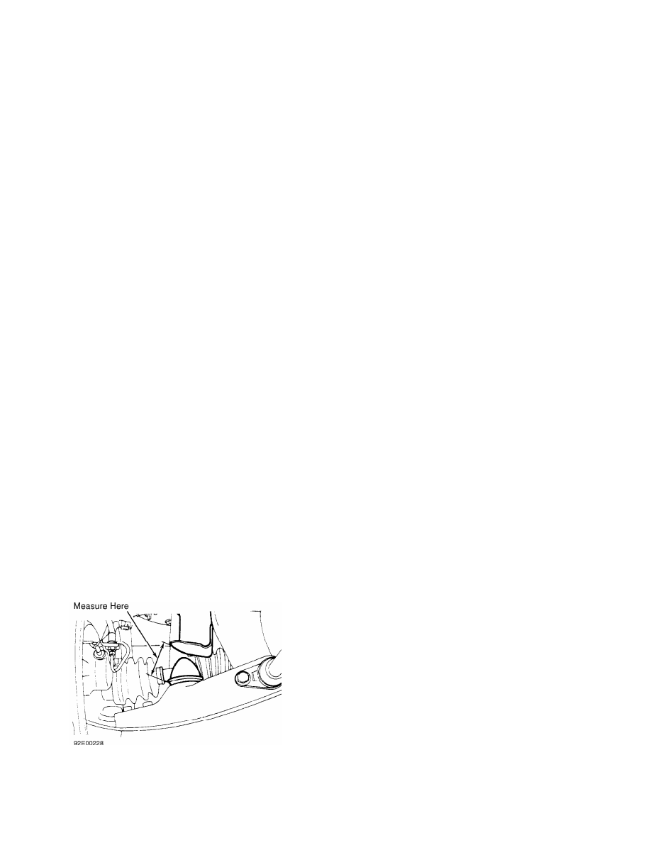
(2) - Distance between lower control bump stopper
and bracket. See Fig. 1.
RIDING HEIGHT SPECIFICATIONS 1992 (FRONT) ( 1)
Application In. (mm)
Montero . . . . .. 0.83-0.91 (21.0-23.0)
Pickup 4WD & Ram-50 4WD . . . 3.11 (79.0)
(1) - Distance between lower control bumper and
bracket.
Fig. 1: Measuring Front Riding Height (Typical 4WD)
Courtesy of Mitsubishi Motor Sales of America.
SCHEDULED SERVICES
1991 Mitsubishi Montero
1987-95 MAINTENANCE
Mitsubishi Maintenance & Service Intervals
Montero
* PLEASE READ THIS FIRST *
NOTE: All SERVICE SCHEDULES are listed for normal service
vehicles. If vehicle is operated under severe service
conditions, see
SEVERE SERVICE REQUIREMENTS (PERFORM W/SERVICE SCHEDULES)
for items requiring additional maintenance.
NOTE: This article contains scheduled maintenance service
information. Fluid types and capacities listed with each
service in this article are only those necessary to perform
that scheduled service. For specifications pertaining to
fluid capacities for the entire vehicle, fuse and circuit
breaker identification, wheel and tire size, battery type,
warranty information, or model identification refer to the
MAINTENANCE INFORMATION article in this section.
CAUTIONS & WARNINGS
SUPPLEMENTAL RESTRAINT SYSTEM (AIR BAG)
NOTE: See the AIR BAG RESTRAINT SYSTEM article in the
ACCESSORIES/SAFETY EQUIPMENT Section.
Modifications or improper maintenance, including incorrect
removal and installation of the Supplemental Restraint System (SRS),
can adversely affect system performance. DO NOT cover, obstruct or
change the steering wheel horn pad in any way, as such action could
cause improper function of the system. Use only plain water when
cleaning the horn pad. Solvents or cleaners could adversely affect the
air bag cover and cause improper deployment of the system.
WARNING: To avoid injury from accidental air bag deployment, read and
carefully follow all warnings and service precautions. See
appropriate AIR BAG RESTRAINT SYSTEM article in the
ACCESSORIES/SAFETY EQUIPMENT section.
CAUTION: Disconnect negative battery cable before servicing any air
bag system, steering column or passenger side dash
component. After any repair, turn ignition key to the ON
position from passenger’s side of vehicle in case of
accidental air bag inflation
AIR CONDITIONING SERVICING
WARNING: R-134a service equipment or vehicle A/C systems SHOULD NOT
be pressure tested or leak tested with compressed air. Some
mixtures of air/R134a have shown to be combustible at
elevated pressures. These mixtures are dangerous and may
cause fire and/or explosions. See the appropriate
A/C SYSTEM GENERAL SERVICING article in the AIR CONDITIONING
& HEAT section.
Нет комментариевНе стесняйтесь поделиться с нами вашим ценным мнением.
Текст