Mitsubishi Galant (2004+). Manual — part 945
MULTIPORT FUEL INJECTION (MFI) DIAGNOSIS
TSB Revision
MULTIPORT FUEL INJECTION (MFI) <2.4L ENGINE>
13A-597
DTC P0431: Warm up catalyst Efficiency Below Threshold (cylinder 2, 3)
.
TECHNICAL DESCRIPTION
• The signal from the rear heated oxygen sensor
differs from the front heated oxygen sensor. That
is because the catalytic converter purifies
exhaust gas. When the catalytic converter has
deteriorated, the signal from the front heated oxy-
gen sensor becomes similar to the rear heated
oxygen sensor.
• The PCM compares the output of the front and
rear heated oxygen sensor signals.
.
DESCRIPTIONS OF MONITOR METHODS
Front and rear heated oxygen sensor rich/lean
switching frequencies are nearly equal.
.
MONITOR EXECUTION
Continuous
.
MONITOR EXECUTION CONDITIONS (Other
monitor and Sensor)
Other Monitor (There is no temporary DTC stored
in memory for the item monitored below)
• Heated oxygen sensor (front) monitor
• Heated oxygen sensor (rear) monitor
• Heated oxygen sensor heater (front) monitor
• Heated oxygen sensor heater (rear) monitor
• Misfire monitor
• Fuel system monitor
• Air/fuel ratio feedback monitor
Sensor (The sensor below is determined to be
normal)
• Mass airflow sensor
• Engine coolant temperature sensor
• Intake air temperature sensor
• Barometric pressure sensor
• Throttle position sensor
• Accelerator pedal position sensor
.
MULTIPORT FUEL INJECTION (MFI) DIAGNOSIS
TSB Revision
MULTIPORT FUEL INJECTION (MFI) <2.4L ENGINE>
13A-598
DTC SET CONDITIONS
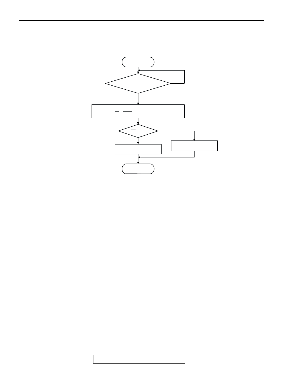
Logic Flow Chart
.
Check Conditions
• Engine speed is lower than 3,000 r/min.
• Accelerator pedal is open.
• Mass airflow is between 14 and 45 g/sec.
• More than 3 seconds have elapsed after the
above-mentioned three conditions have been
met.
• Intake air temperature is higher than −10°C
(14
°F).
• Barometric pressure is higher than 76 kPa (22.4
in.Hg).
• Under the closed loop air/fuel ratio control.
• Vehicle speed is 1.5 km/h (1.0 mph) or more.
• The PCM monitors for this condition for 5 cycles
of 10 seconds each during the drive cycle.
• Short-term fuel trim is higher than −25 percent
and lower than +25 percent.
• The cumulative mass airflow is higher than 1,638
g.
Judgment Criteria
• The cylinder 2, 3 heated oxygen sensor (rear)
signal frequency divided by cylinder 2, 3 heated
oxygen sensor (front) signal frequency = 0.7 or
more. <Federal>
or
• The cylinder 2, 3 heated oxygen sensor (rear)
signal frequency divided by cylinder 2, 3 heated
oxygen sensor (front) signal frequency = 0.6 or
more. <California>
.
OBD-II DRIVE CYCLE PATTERN
Refer to Diagnostic Function
− OBD-II Drive Cycle −
Procedure 3
− Catalytic Converter Monitor
.
TROUBLESHOOTING HINTS (The most likely
causes for this code to be set are:)
• Cylinder 2, 3 side catalytic converter deteriorated.
• Cylinder 2, 3 heated oxygen sensor failed.
• Exhaust leak.
• PCM failed.
START
MONITORING
CONDITIONS
MALFUNCTION
GOOD
END
NO
NO
YES
YES
Rf > R0
CALCULATE AVERAGE FREQUENCY
RATIO (Rf = Fr/Ff) OF SPECIFIED TIMES
R0: AVERAGE THRESHOLD VALUE.
AK302038
MULTIPORT FUEL INJECTION (MFI) DIAGNOSIS
TSB Revision
MULTIPORT FUEL INJECTION (MFI) <2.4L ENGINE>
13A-599
DIAGNOSIS
Required Special Tools:
• MB991958: Scan tool (MUT-III Sub Assembly)
• MB991824: V.C.I.
• MB991827: USB Cable
• MB991910: Main Harness A
STEP 1. Check for exhaust leak.
Q: Are there any abnormalities?
YES : Repair it. Then go to Step 7.
NO : Go to Step 2.
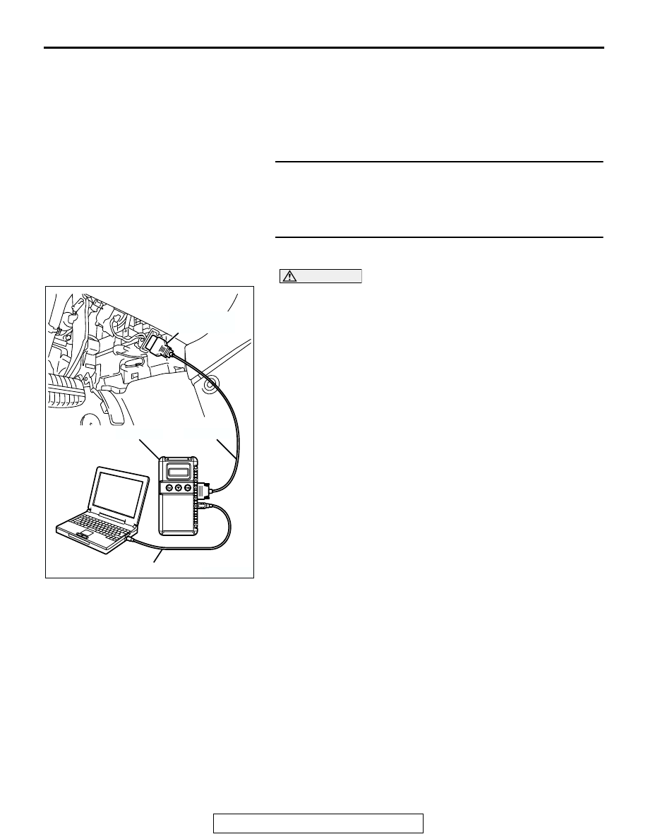
STEP 2. Using scan tool MB991958, check data list item 59:
Cylinder 2, 3 Heated Oxygen Sensor (rear).
CAUTION
To prevent damage to scan tool MB991958, always turn the
ignition switch to the "LOCK" (OFF) position before con-
necting or disconnecting scan tool MB991958.
(1) Connect scan tool MB991958 to the data link connector.
(2) Start the engine and run at idle.
(3) Set scan tool MB991958 to the data reading mode for item
59, Cylinder 2, 3 Heated Oxygen Sensor (rear).
• Warming up the engine. When the engine is revved, the
output voltage should repeat 0 volt and 0.6 to 1.0 volt
alternately.
(4) Turn the ignition switch to the "LOCK" (OFF) position.
Q: Is the sensor operating properly?
YES : Go to Step 3.
NO : Refer to DTC P0156
− Cylinder 2, 3 Heated Oxygen
Sensor Circuit (Sensor 2)
−
Cylinder 2, 3 Heated Oxygen Sensor Circuit Low
Voltage (Sensor 2)
, DTC P0158
− Cylinder
2, 3 Heated Oxygen Sensor Circuit High Voltage
(Sensor 2)
, DTC P0159
− Cylinder 2, 3
Heated Oxygen Sensor Circuit Slow Response
(Sensor 2)
AK303804AB
MB991910
DATA LINK
CONNECTOR
MB991824
MB991827
MULTIPORT FUEL INJECTION (MFI) DIAGNOSIS
TSB Revision
MULTIPORT FUEL INJECTION (MFI) <2.4L ENGINE>
13A-600
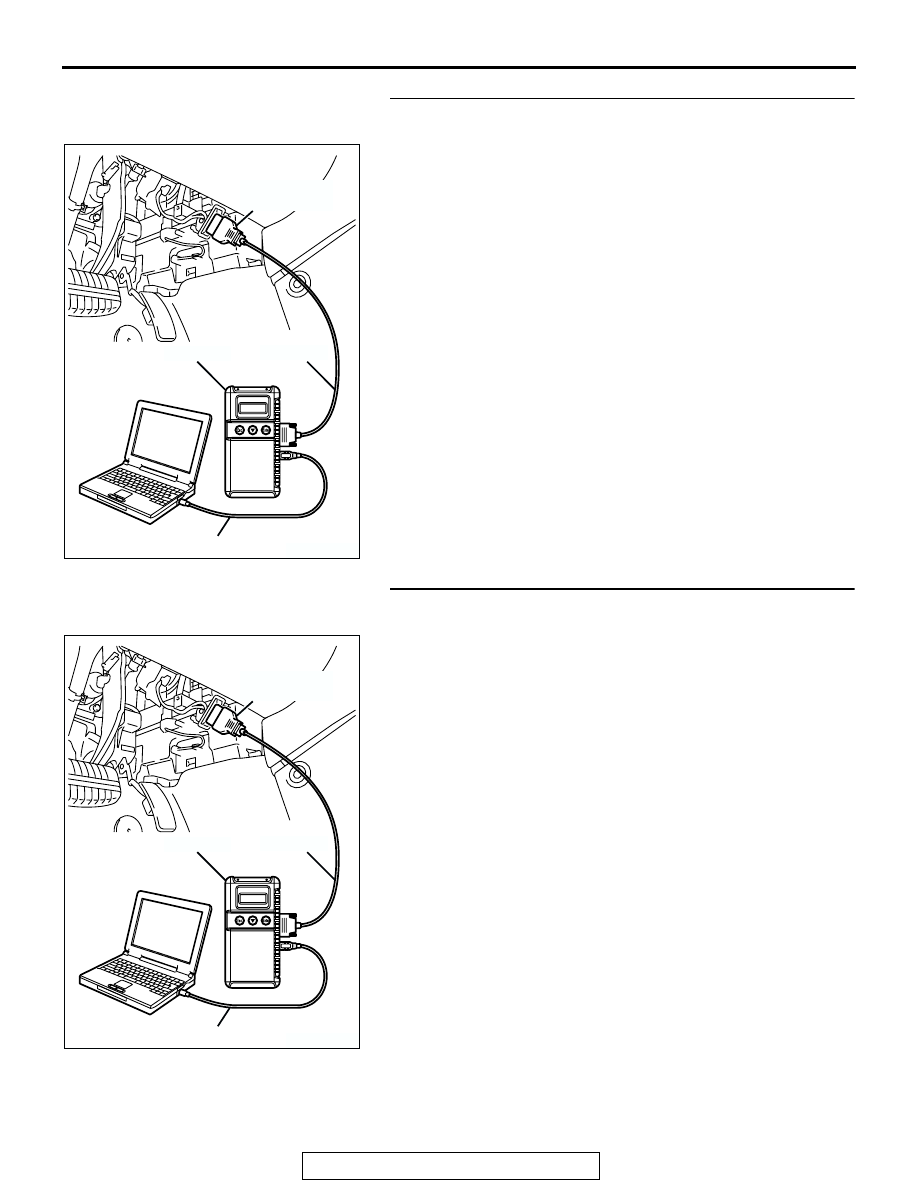
STEP 3. Using scan tool MB991958, check data list item 11:
Cylinder 2, 3 Heated Oxygen Sensor (front).
(1) Start the engine and run at idle.
(2) Set scan tool MB991958 to the data reading mode for item
11, Cylinder 2, 3 Heated Oxygen Sensor (front).
• Warming up the engine. When the engine is revved, the
output voltage should be 0.6 to 1.0 volt.
(3) Turn the ignition switch to the "LOCK" (OFF) position.
Q: Is the sensor operating properly?
YES : Go to Step 4.
NO : Refer to DTC P0150
− Cylinder 2, 3 Heated Oxygen
Sensor Circuit (Sensor 1)
−
Cylinder 2, 3 Heated Oxygen Sensor Circuit Low
Voltage (Sensor 1)
, DTC P0152
− Cylinder
2, 3 Heated Oxygen Sensor Circuit High Voltage
(Sensor 1)
, DTC P0153
− Cylinder 2, 3
Heated Oxygen Sensor Circuit Slow Response
(Sensor 1)
, DTC P0154
− Cylinder 2, 3
Heated Oxygen Sensor Circuit No Activity Detected
(Sensor 1)
STEP 4. Using scan tool MB991958, check data list item 11:
Cylinder 2, 3 Heated Oxygen Sensor (front).
(1) Start the engine and run at idle.
(2) Set scan tool MB991958 to the data reading mode for item
11, Cylinder 2, 3 Heated Oxygen Sensor (front).
(3) Keep the engine speed at 2,000 r/min.
• 0 − 0.4 and 0.6 − 1.0 volt should alternate 15 times or
more within 10 seconds.
(4) Turn the ignition switch to the "LOCK" (OFF) position.
Q: Is the sensor operating properly?
YES : Go to Step 5.
NO : Replace the cylinder 2, 3 heated oxygen sensor
(front). Then go to Step 7.
AK303804AB
MB991910
DATA LINK
CONNECTOR
MB991824
MB991827
AK303804AB
MB991910
DATA LINK
CONNECTOR
MB991824
MB991827
Нет комментариевНе стесняйтесь поделиться с нами вашим ценным мнением.
Текст