Mitsubishi Eclipse / Eclipse Spyder (2000-2002). Service and repair manual — part 406
SPECIAL TOOLS
TSB Revision
MANUAL TRANSAXLE
22A-9
SPECIA L TO O LS
M1221000600520
O N -VEH IC LE SERVIC E
TRANSAXLE OIL LEVEL CHECK
M1221000900349
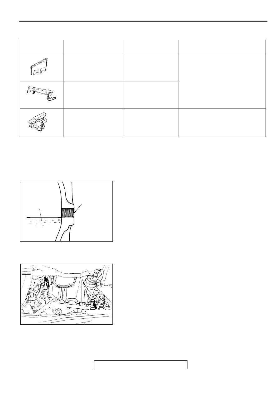
1. Remove the filler plug.
2. Check that the oil level is up to the lower edge of the filler
plug hole.
3. Check that the oil is not noticeably dirty, and that it has a
suitable viscosity.
4. Tighten the filler plug to the specified torque.
Tightening torque: 32
±
2 N
⋅
m (24
±
1 ft-lb)
TRANSAXLE OIL REPLACEMENT
M1221001000253
1. Remove the filler plug.
2. Remove the drain plug and drain the oil.
3. Tighten the drain plug to the specified torque.
Tightening torque: 32
±
2 N
⋅
m (24
±
1 ft-lb)
4. Fill with gear oil SAE 75W
−
90W or 75W
−
85W conforming
to API classification GL-4 till the level comes to the lower
portion of filler plug hole.
Quantity:
<F5M42> 2.2 dm
3
(2.3 quarts)
<F5M51> 2.8 dm
3
(3.0 quarts)
5. Tighten the filler plug to the specified torque.
Tightening torque: 32
±
2 N
⋅
m (24
±
1 ft-lb)
TOOL
TOOL NUMBER AND
NAME
SUPERSESSION
APPLICATION
MB991453
Engine hanger
-
Supporting the engine assembly
during removal and installation of the
transaxle
GENERAL SERVICE
TOOL MZ203827
Engine lifter
General service tool
MB991113
Steering linkage puller
MB990635
Tie rod end and lower arm
disconnection
MB991453
MZ203827
MB990635
AC001592
TRANSMISSION
OIL
FILLER PLUG
HOLE
AB
AC001597
DRIVESHAFT <LH>
DRAIN PLUG
FILLE RPLUG
AB
TRANSAXLE CONTROL
TSB Revision
MANUAL TRANSAXLE
22A-10
TR A N SA XLE C O N TR O L
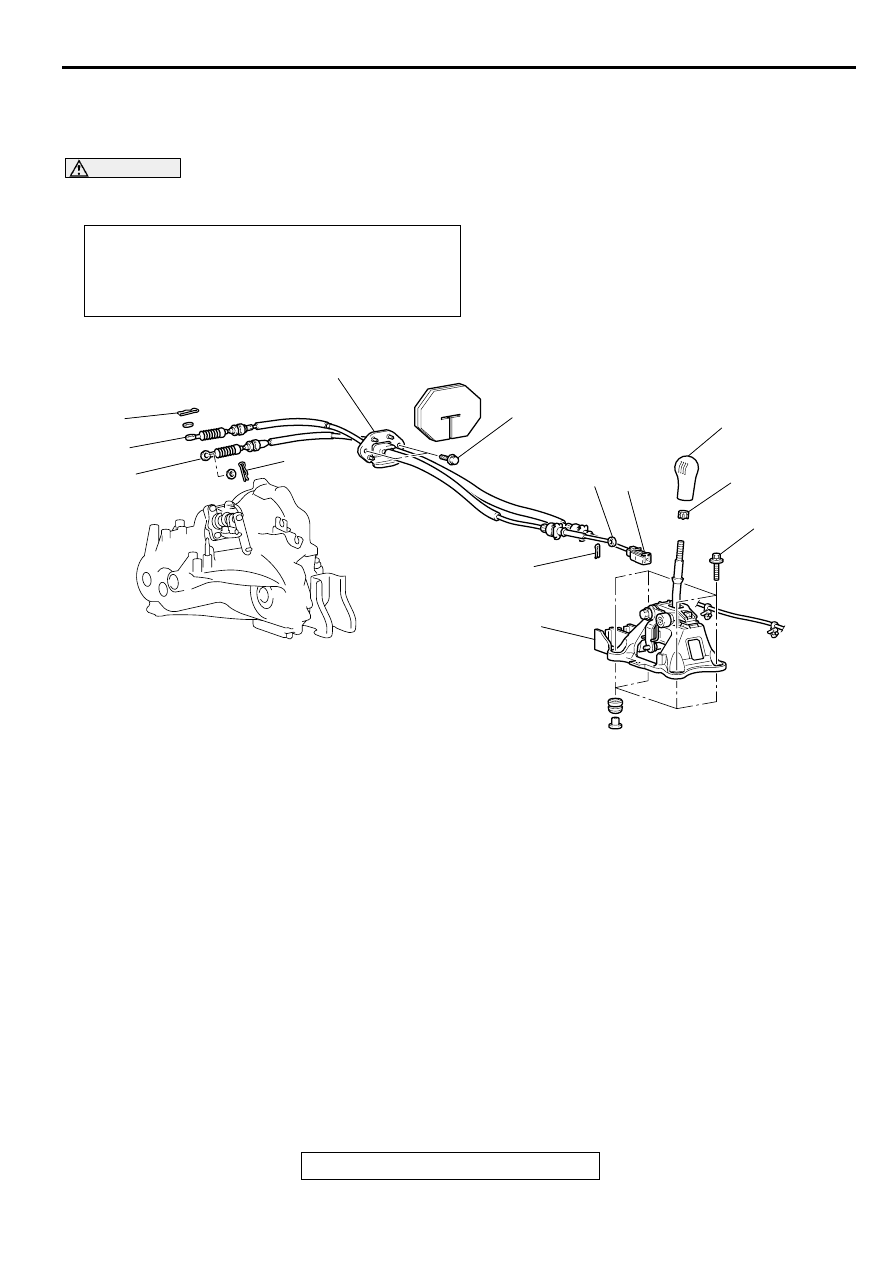
REMOVAL AND INSTALLATION
M1221003800415
WARNING
Be careful not to subject the SRS-ECU to any shocks during removal and installation of the
shift cable and select cable assembly.
Pre-removal and Post-installation Operation
•
Air Cleaner Assembly Removal and Installation (Refer to
GROUP 15, Air Cleaner
•
Battery and Battery Tray Removal and Installation. (Refer
to GROUP 54A, Battery
AC001625
1
2
3
4
5
12 ± 2 N·m
102 ± 22 in-lb
9
12 ± 2 N·m
102 ± 22 in-lb
6
7
8
6
10
AB
SHIFT CABLE AND SELECT
CABLE ASSEMBLY REMOVAL
STEPS
>>B<<
1.
SHIFT KNOB
>>B<<
2.
SLEEVE
•
FLOOR CONSOLE BOX (REFER
TO GROUP 52A, FLOOR
CONSOLE
3.
SNAP PIN
4.
SELECT CABLE CONNECTION
(SHIFT LEVER SIDE)
<<A>>
>>A<<
5.
SHIFT CABLE CONNECTION
(SHIFT LEVER SIDE)
6.
SNAP PIN
>>C<<
7.
SELECT CABLE CONNECTION
(TRANSAXLE SIDE)
>>C<<
8.
SHIFT CABLE CONNECTION
(TRANSAXLE SIDE)
•
HEATER/COOLER UNIT (REFER
TO GROUP 55, HEATER/
COOLER UNIT, HEATER CORE
AND EVAPORATOR
.)
>>C<<
9.
SHIFT CABLE AND SELECT
CABLE ASSEMBLY
SHIFT LEVER ASSEMBLY
REMOVAL STEPS
>>B<<
1.
SHIFT KNOB
>>B<<
2.
SLEEVE
•
FLOOR CONSOLE BOX (REFER
TO GROUP 52A, FLOOR
CONSOLE
3.
SNAP PIN
4.
SELECT CABLE CONNECTION
(SHIFT LEVER SIDE)
SHIFT CABLE AND SELECT
CABLE ASSEMBLY REMOVAL
STEPS (Continued)
TRANSAXLE CONTROL
TSB Revision
MANUAL TRANSAXLE
22A-11
REMOVAL SERVICE POINT
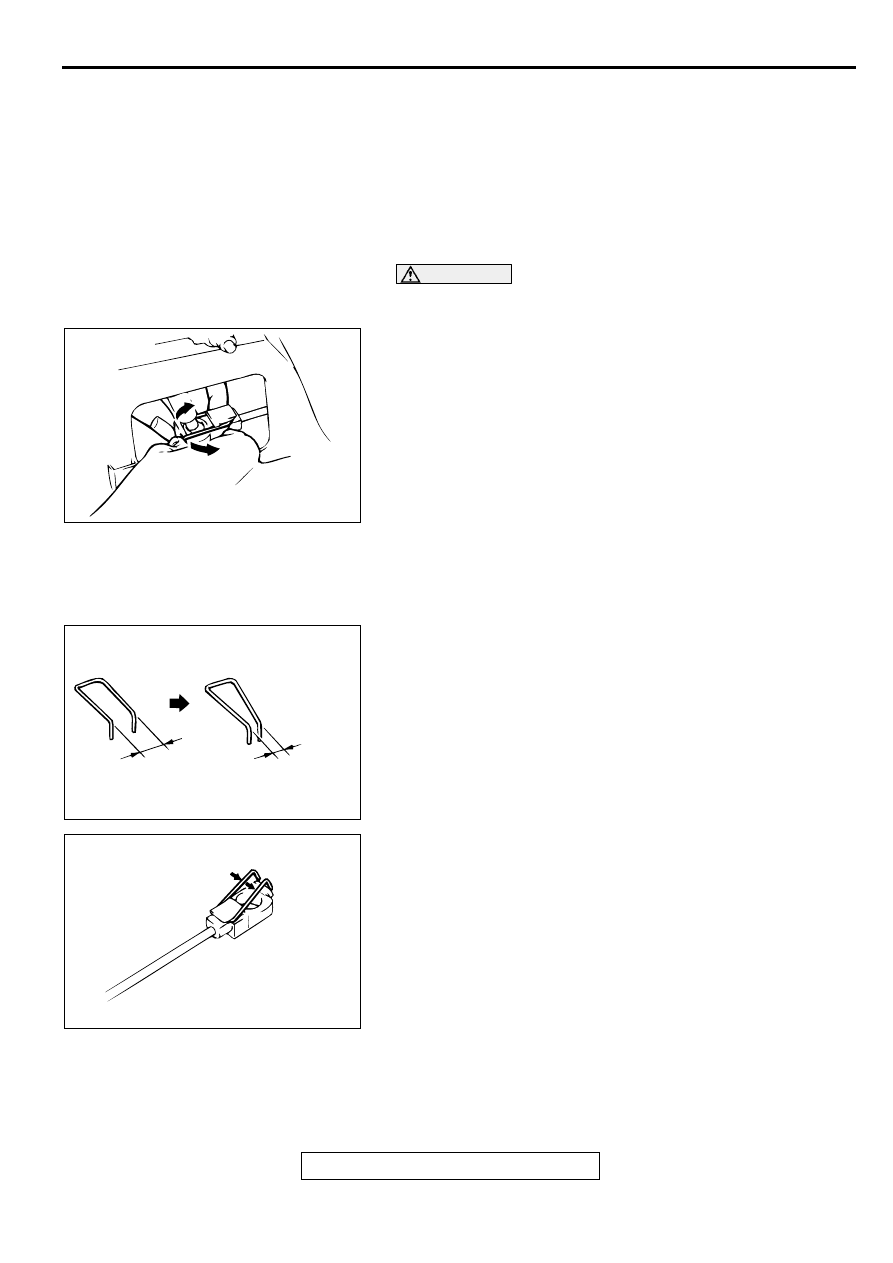
<<A>> SHIFT CABLE CONNECTION (SHIFT LEVER SIDE)
REMOVAL
CAUTION
Be careful not to disengage the clip from the shift cable or
deform it.
Expand the clip at the shift cable end toward the arrow
direction, and remove the cable from the shift lever by pushing
the shift cable down.
INSTALLATION SERVICE POINTS
>>A<< SHIFT CABLE CONNECTION (SHIFT LEVER SIDE)
INSTALLATION
1. Make sure that there is no excessive play at the shift cable
end clip. If there is an excessive play or the clip is
disengaged from the shift cable end, check the clip opening
gap. If the gap is more than 9.5 mm (0.37 inch), deform the
clip until the gap reaches 5 to 8 mm (0.20 to 0.31 inch).
2. Engage the clip with the shift cable hook securely, and push
the clip with your thumbs until it clicks in place.
3. Install the shift cable to the shift lever.
<<A>>
>>A<<
5.
SHIFT CABLE CONNECTION
(SHIFT LEVER SIDE)
10. SHIFT LEVER ASSEMBLY
SHIFT LEVER ASSEMBLY
REMOVAL STEPS (Continued)
AC001673
AC001661
9.5
(0.37)
5 - 8
(0.20 - 0.31)
mm
(in)
AB
AC001662
TRANSAXLE CONTROL
TSB Revision
MANUAL TRANSAXLE
22A-12
>>B<< SLEEVE/SHIFT KNOB INSTALLATION
1. Place the sleeve over the shift lever end.
2. Place the shift knob over the sleeve.
3. Screw in the shift knob. When the shift knob is hard to turn
(approximately seven turns), screw in the shift knob four
additional turns until its shift pattern faces forward.
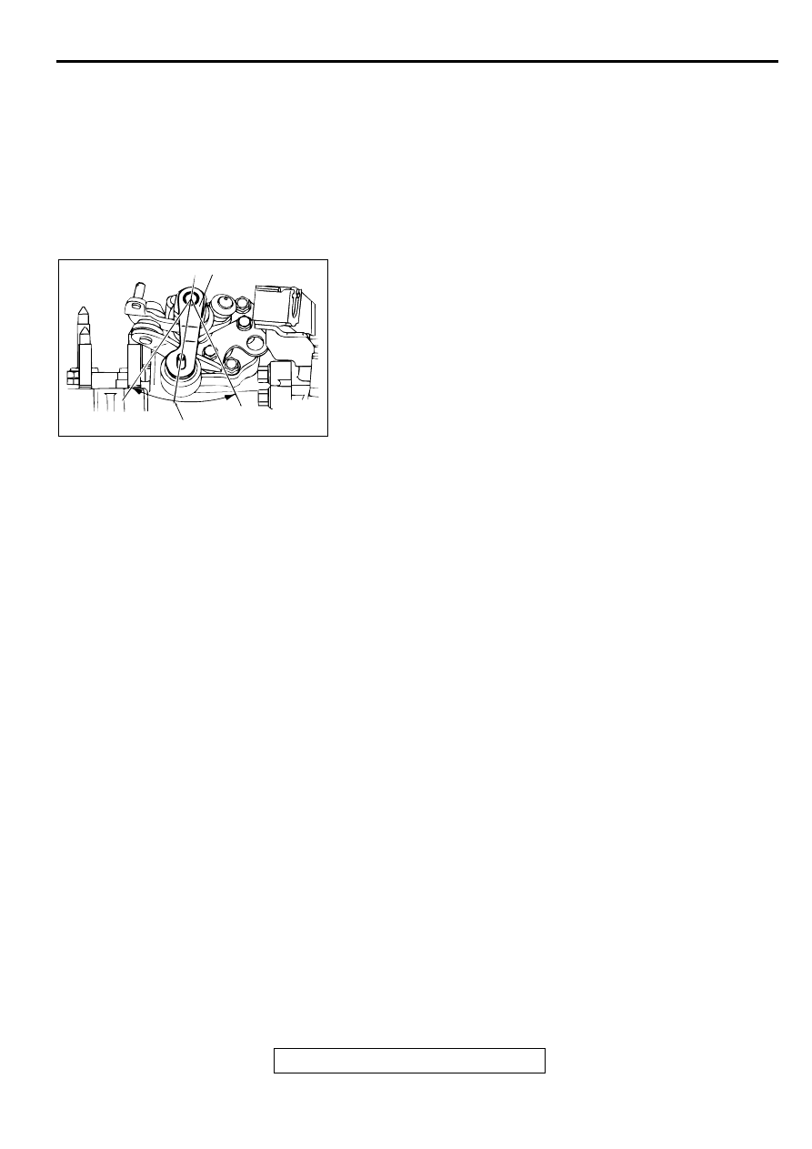
>>C<< SHIFT CABLE AND SELECT CABLE ASSEMBLY/
SHIFT CABLE CONNECTION/SELECT CABLE
CONNECTION
1. Set the transaxle side shift lever and the passenger
compartment side shift lever to the neutral position.
2. For the transaxle side, the white and yellow paint marks on
the shift and select cable ends should face the snap pins.
3. Move the shift lever to all positions and check that the
operation is smooth.
AC001663 AB
NEUTRAL POSITION
SHIFT LEVER
Нет комментариевНе стесняйтесь поделиться с нами вашим ценным мнением.
Текст