Mitsubishi Eclipse / Eclipse Spyder (2000-2002). Service and repair manual — part 20
HOW TO DIAGNOSE
TSB Revision
GENERAL <ELECTRICAL>
00E-13
GENERAL ELECTRICAL SYSTEM CHECK
M1001005300034
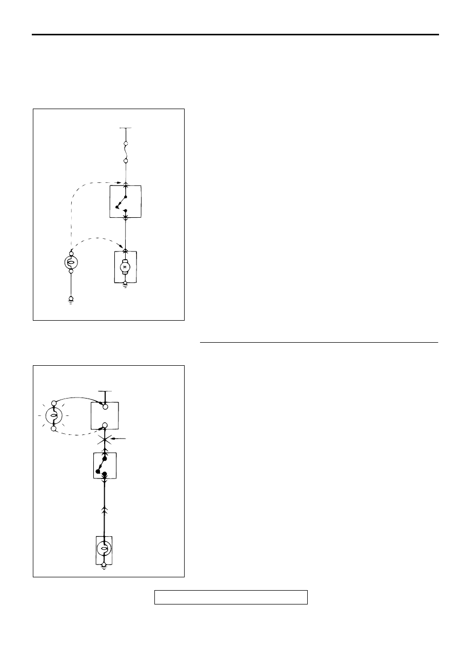
A circuit consists of the power supply, switch, relay, load,
ground, etc. There are various methods to check a circuit
including an overall check, voltage check, short-circuit check,
and continuity check. Each of the methods briefly described
below apply only to circuits similar to the illustration.
1. VOLTAGE CHECK
(1) Ground one lead wire of the test light. If a voltmeter is
used instead of the test light, ground the grounding side
lead wire.
(2) Connect the other lead wire of the test light to the power
side terminal of the switch connector. The test light
should come on or the voltmeter should indicate a
voltage.
(3) Then, connect the test light or voltmeter to the motor
connector. The test light should not come on, or the
voltmeter should indicate no voltage. When the switch is
turned on in this state, the test light should come on, or
the voltmeter should indicate a voltage, with motor
starting to run.
(4) The circuit illustrated here is normal. If there is any
problem, such as the motor failing to run, check voltages
beginning at the connector nearest to the motor until the
faulty part is identified.
2. SHORT-CIRCUIT CHECK
Because the fuse has blown, it is probable that there is a
short circuit. Follow the procedures below to narrow down
the short-circuit location.
STEP 1. Remove the blown fuse and connect the test light
across the fuse terminals (Switch: OFF).
Q: Does the test light illuminate?
YES : Short-circuit exists between the fuse block and the
switch.Repair the harness between the fuse block
and the switch.
NO : Go to Step 2.
ACX00956 AB
POWER SUPPLY
FUSE
SWITCH
MOTOR
(3)
ON (2)
OFF
(1)
TEST LIGHT
(OR
VOLTMETER)
ACX00957 AB
POWER SUPPLY
SWITCH
OFF
ILLUMINATION
LIGHT
TEST
LIGHT
FUSE BLOCK
(REMOVE
THE FUSE)
SHORT-CIRCUIT
LOCATION
HOW TO DIAGNOSE
TSB Revision
GENERAL <ELECTRICAL>
00E-14
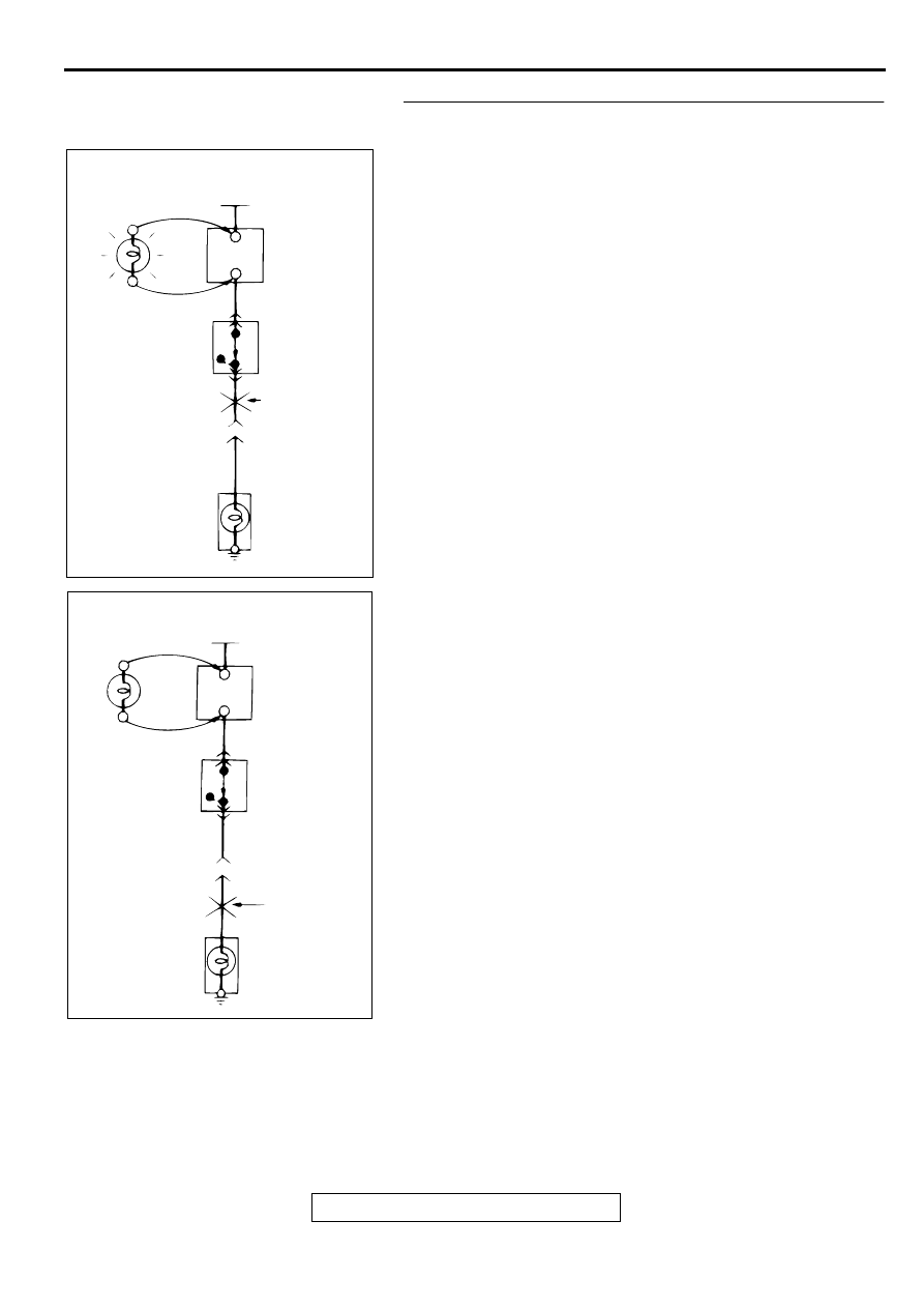
STEP 2. Switch on the switch and disconnect the
illumination light connector.
Q: Does the test light illuminate?
YES : Short-circuit exists between the switch and the
connector. Repair the harness between the switch
and the connector.
NO : Short-circuit exists between the connector and the
illumination light. Repair the harness between the
switch and the connector.
ACX00958 AB
POWER SUPPLY
SWITCH
ON
ILLUMINATION
LIGHT
TEST
LIGHT
FUSE BLOCK
(REMOVE
THE FUSE)
DISCONNECT
THE LOAD
SHORT-CIRCUIT
LOCATION
ACX00959 AB
POWER SUPPLY
SWITCH
ON
ILLUMINATION
LIGHT
TEST
LIGHT
FUSE BLOCK
(REMOVE
THE FUSE)
DISCONNECT
THE LOAD
SHORT-CIRCUIT
LOCATION
HOW TO DIAGNOSE
TSB Revision
GENERAL <ELECTRICAL>
00E-15
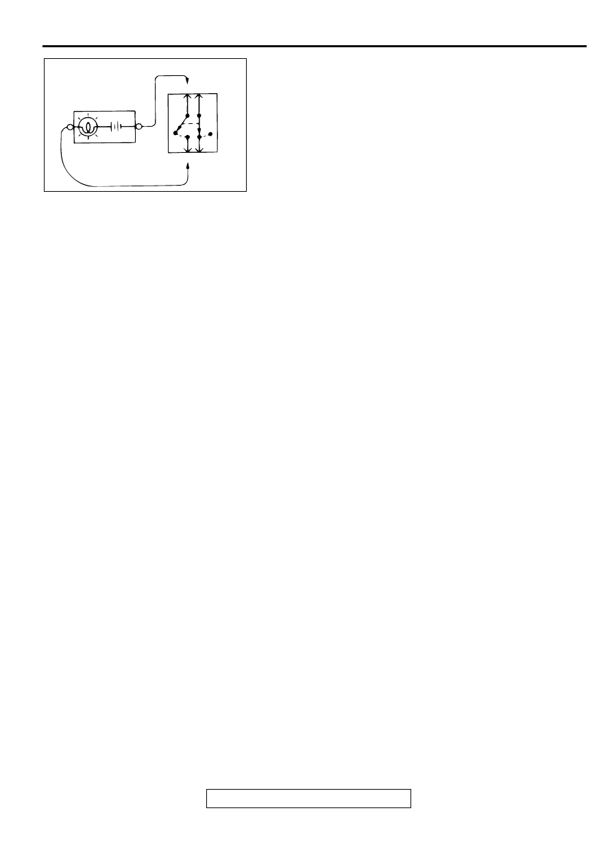
3. CONTINUITY CHECK
(1) When the switch is in the "OFF" position, the self-
powered test light should illuminate or the ohmmeter
should read 0 ohm, only when the contact points of
terminals 1 and 2 are connected.
(2) When the switch is the "ON" position, the self-powered
test light should come on or the ohmmeter should read 0
ohm, only when the contact points of terminals 3 and 4
are connected.
ACX00960 AB
SELF POWER TEST
LIGHT (OR OHMMETER)
1 4
2 3
ON
OFF
ON
OFF
NOTES
Нет комментариевНе стесняйтесь поделиться с нами вашим ценным мнением.
Текст