Mitsubishi Eclipse / Eclipse Spyder (2000-2002). Service and repair manual — part 493

AUTOMATIC TRANSAXLE DIAGNOSIS
TSB Revision
AUTOMATIC TRANSAXLE
23A-264
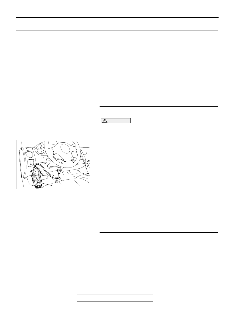
STEP 7. Using scan tool MB991502, check data list item 11:
Throttle position sensor.
CAUTION
To prevent damage to scan tool MB991502, always turn the
ignition switch to "LOCK" (OFF) position before
connecting or disconnecting scan tool MB991502.
(1) Connect scan tool MB991502 to the data link connector.
(2) Turn the ignition switch to "ON" position.
(3) Set scan tool MB991502 to data reading mode for item 11:
Throttle Position Sensor.
•
With the throttle valve in idle position, voltage should be
between 535 and 735 mV.
•
With the throttle valve in full-open position, voltage
should be between 4,500 and 5,500 mV.
(4) Turn the ignition switch to "LOCK" (OFF) position.
Q: Is the sensor operating properly?
YES : Go to Step 8.
NO : Check the throttle position sensor. Refer to
, code number 11, 12, 14: Throttle
Position Sensor System. Then check the symptom.
STEP 8. Disassemble and clean the valve body.
Check the O-ring installation bolts for looseness and the valve
body for damage. Repair or replace the faulty parts. Refer to
GROUP 23B, Valve Body
.
Q: Is the repair possible and the symptom eliminated?
YES : Diagnosis is complete.
NO : Replace the valve body assembly. Then check the
symptom. Go to Step 9.
STEP 9. Replace the PCM.
Q: Is the symptom eliminated?
YES : Diagnosis is complete.
NO : Start over at Step 1.
AC001252
MB991502
16 PIN
AB
AC001860 AB
VALVE
BODY
ASSEMBLY
AUTOMATIC TRANSAXLE DIAGNOSIS
TSB Revision
AUTOMATIC TRANSAXLE
23A-265
INSPECTION PROCEDURE 7: Shift Shocks when Shifting from "N" to "R" and Long Delay
COMMENT
If abnormal shocks or delay of two seconds or more
occur when the selector lever is shifted from "N" to
"R" range while the engine is idling, the cause is
probably abnormal reverse clutch pressure or low-
reverse brake pressure, or a malfunction of the
reverse clutch, low-reverse brake, valve body or
throttle position sensor.
TROUBLESHOOTING HINTS (The most likely
causes for this code to be set:)
•
Abnormal reverse clutch pressure
•
Abnormal low-reverse brake pressure
•
Malfunction of the low-reverse solenoid valve
•
Malfunction of the reverse clutch
•
Malfunction of the low-reverse brake
•
Malfunction of the valve body
•
Malfunction of the throttle position sensor
•
Malfunction of the PCM
DIAGNOSIS
REQUIRED SPECIAL TOOL:
MB991502: Scan Tool (MUT-II)
STEP 1. Using scan tool MB991502, check actuator test
item 01: Low-Reverse Solenoid Valve.
CAUTION
To prevent damage to scan tool MB991502, always turn the
ignition switch to "LOCK" (OFF) position before
connecting or disconnecting scan tool MB991502.
(1) Connect scan tool MB991502 to the data link connector.
(2) Turn the ignition switch to "ON" position.
(3) Set scan tool MB991502 to actuator test mode for item 01:
Low-Reverse Solenoid Valve.
•
An operation sound should be heard from solenoid
valve when solenoid valve is operated.
(4) Turn the ignition switch to "LOCK" (OFF) position.
Q: Is the solenoid valve operating properly?
YES : Go to Step 2.
NO : Repair or replace the low-reverse solenoid valve.
Refer to GROUP 23B, Valve Body
. Then
confirm that the symptom is eliminated.
STEP 2. Check when shift shocks occur.
Q: When the shift shocks occur?
When engaging from N to R : Go to Step 3.
When the vehicle starts moving : Go to Step 7.
STEP 3. Check the hydraulic pressure (for reverse clutch).
Measure the hydraulic pressure for reverse clutch when the
selector lever is at the "R" range. Check if the hydraulic
pressure is within the standard value. Refer to
Hydraulic Pressure Test.
Q: Is the hydraulic pressure within the standard value?
YES : Go to Step 4.
NO : Go to Step 9.
AC001252
MB991502
16 PIN
AD
AUTOMATIC TRANSAXLE DIAGNOSIS
TSB Revision
AUTOMATIC TRANSAXLE
23A-266
STEP 4. Check the hydraulic pressure (for low-reverse
brake).
Measure the hydraulic pressure for low-reverse brake when the
selector lever is at the "R" range. Check if the hydraulic
pressure is within the standard value. Refer to
Hydraulic Pressure Test.
Q: Is the hydraulic pressure within the standard value?
YES : Go to Step 5.
NO : Go to Step 9.
STEP 5. Check the reverse clutch system and low-reverse
brake system.
(1) Remove the valve body cover and valve body. Refer to
, Transaxle Assembly and GROUP 23B,
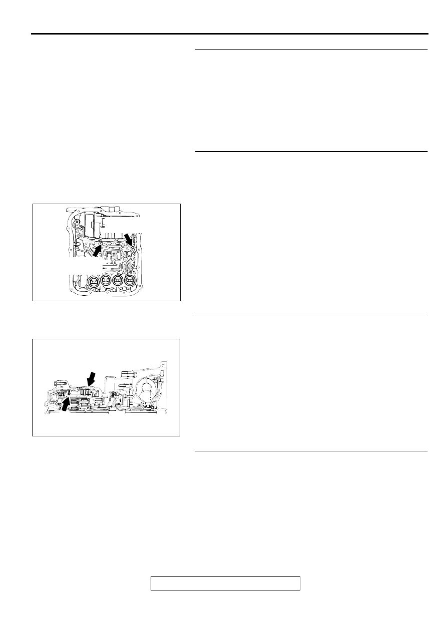
(2) Blow compressed air into the reverse clutch oil orifice of the
transaxle case, and check if the reverse clutch piston
moves and air pressures are maintained in that condition.
Repeat for the low-reverse brake.
Q: Are both air pressures maintained?
YES : Go to Step 6.
NO : Go to Step 9.
STEP 6. Check the reverse clutch and low-reverse brake.
(1) Remove the transaxle assembly.
(2) Check the facing for seizure and the piston seal ring for
damage and interference with the retainer. Repair or
replace the faulty parts. Refer to GROUP 23B, Transaxle
, Reverse and Overdrive Clutch
. Then
check for the symptom.
Q: Is the symptom eliminated?
YES : Diagnosis is complete.
NO : Go to Step 10.
STEP 7. Check shift shocks.
Q: Do shift shocks occur sometimes?
YES : Go to Step 8.
NO : Go to Step 9.
AC001862
REVERSE CLUTCH
OIL ORIFICE
LOW-REVERSE
BRAKE OIL ORIFICE
AB
AC001863 AB
LOW-REVERSE BRAKE
REVERSE CLUTCH
AUTOMATIC TRANSAXLE DIAGNOSIS
TSB Revision
AUTOMATIC TRANSAXLE
23A-267
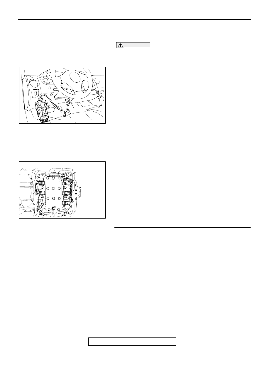
STEP 8. Using scan tool MB991502, check data list item 11:
Throttle position sensor.
CAUTION
To prevent damage to scan tool MB991502, always turn the
ignition switch to "LOCK" (OFF) position before
connecting or disconnecting scan tool MB991502.
(1) Connect scan tool MB991502 to the data link connector.
(2) Turn the ignition switch to "ON" position.
(3) Set scan tool MB991502 to data reading mode for item 11:
Throttle Position Sensor.
•
With the throttle valve in idle position, voltage should be
between 535 and 735 mV.
•
With the throttle valve in full-open position, voltage
should be between 4,500 and 5,500 mV.
(4) Turn the ignition switch to "LOCK" (OFF) position.
Q: Is the sensor operating properly?
YES : Go to Step 9.
NO : Check the throttle position sensor. Refer to
, code number 11, 12, 14: Throttle
Position Sensor System. Then check the symptom.
STEP 9. Disassemble and clean the valve body.
Check the O-ring installation bolts for looseness and the valve
body for damage. Repair or replace the faulty parts. Refer to
GROUP 23B, Valve Body
.
Q: Is the repair possible and the symptom eliminated?
YES : Diagnosis is complete.
NO : Replace the valve body assembly. Then check the
symptom. Go to Step 10.
STEP 10. Replace the PCM.
Q: Is the symptom eliminated?
YES : Diagnosis is complete.
NO : Start over at Step 1.
AC001252
MB991502
16 PIN
AD
AC001860 AB
VALVE
BODY
ASSEMBLY
Нет комментариевНе стесняйтесь поделиться с нами вашим ценным мнением.
Текст