Mitsubishi Eclipse / Eclipse Spyder (2000-2002). Service and repair manual — part 447
AUTOMATIC TRANSAXLE DIAGNOSIS
TSB Revision
AUTOMATIC TRANSAXLE
23A-79
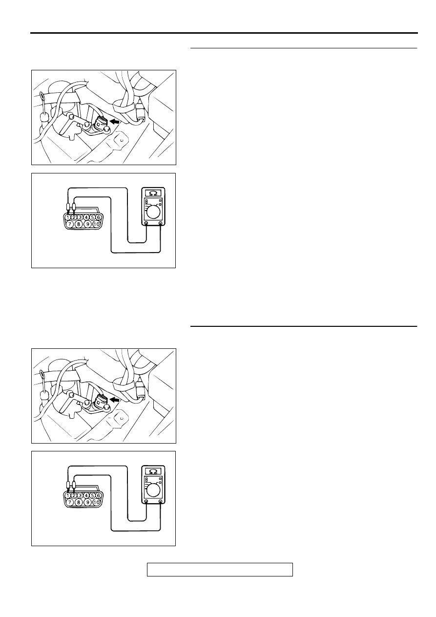
STEP 8. Check the A/T fluid temperature sensor at A/T
control solenoid valve assembly connector B-40.
(1) Disconnect connector B-40 and measure at the sensor
side.
(2) Measure the resistance between terminal 1 and 2.
•
When A/T fluid temperature is 0
°
C (32
°
F), resistance
should be between 16.7 and 20.5 ohm.
•
When A/T fluid temperature is 20
°
C (68
°
F), resistance
should be between 7.3 and 8.9 ohm.
•
When A/T fluid temperature is 40
°
C (104
°
F), resistance
should be between 3.4 and 4.2 ohm.
•
When A/T fluid temperature is 80
°
C (176
°
F), resistance
should be between 1.9 and 2.2 ohm.
•
When A/T fluid temperature is 100
°
C (212
°
F),
resistance should be between 0.57 and 0.69 ohm.
Q: Is the resistance normal?
YES : Go to Step 9.
NO : Replace the A/T fluid temperature sensor. Refer to
GROUP 23B, Transaxle
.
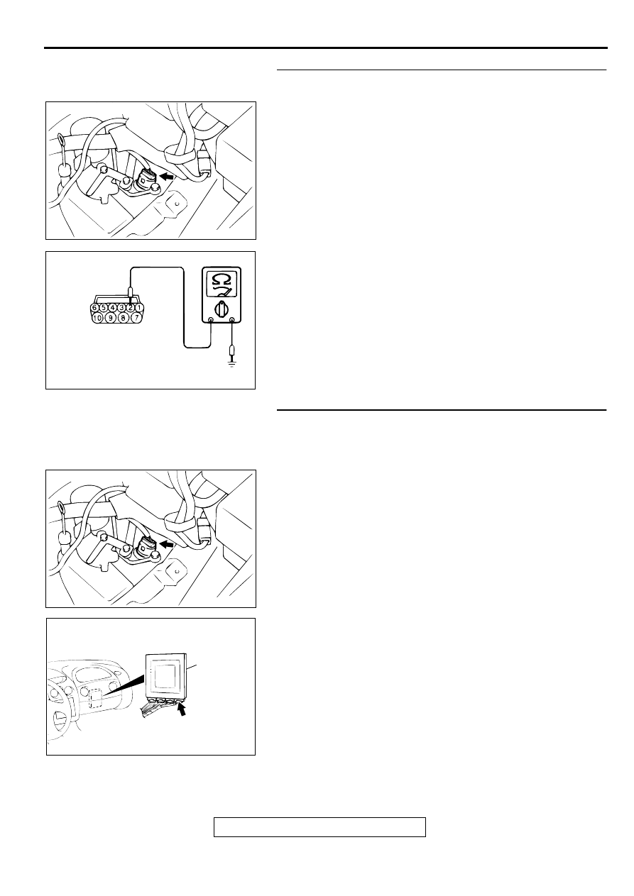
STEP 9. Check the power supply voltage at A/T control
solenoid valve assembly connector B-40.
(1) Disconnect connector B-40 and measure at the harness
side.
(2) Turn the ignition switch to "ON" position.
(3) Measure the voltage between terminal 1 and ground.
•
Voltage should be between 4.5 and 4.9 volts.
(4) Turn the ignition switch to "LOCK" (OFF) position.
Q: Is the voltage normal?
YES : Go to Step 10.
NO : Repair it because of harness open circuit between A/
T control solenoid valve assembly connector B-40
terminal 1 and PCM connector C-61 <2.4L Engine> or
C-63 <3.0L Engine> terminal 124.
ACX02479
CONNECTOR: B-40
AE
ACX02103
HARNESS
CONNECTOR: B-40
AD
ACX02479
CONNECTOR: B-40
AE
ACX02103
HARNESS
CONNECTOR: B-40
AD
AUTOMATIC TRANSAXLE DIAGNOSIS
TSB Revision
AUTOMATIC TRANSAXLE
23A-80
STEP 10. Check the continuity at A/T control solenoid
valve assembly connector B-40.
(1) Disconnect connector B-40 and measure at the harness
side.
(2) Check for the continuity between terminal 2 and ground.
•
Should be less than 2 ohm.
Q: Is the continuity normal?
YES : Go to Step 11.
NO : Repair it because of harness open circuit or damage
between A/T control solenoid valve assembly
connector B-40 terminal 2 and PCM connector C-54
<2.4L Engine> or C-55 <3.0L Engine> terminal 57.
STEP 11. Check harness for damage between A/T control
solenoid valve assembly connector B-40 terminal 1 and
PCM connector C-54 <2.4L Engine> or C-55 <3.0L Engine>
terminal 124.
Q: Is the harness wire in good condition?
YES : Repair it because of harness damage between A/T
control solenoid valve assembly connector B-40
terminal 2 and PCM connector C-64 <2.4L Engine> or
C-65 <3.0L Engine> terminal 57.
NO : Repair it.
ACX02479
CONNECTOR: B-40
AE
ACX02105
HARNESS
CONNECTOR: B-40
AD
ACX02479
CONNECTOR: B-40
AE
AC001657
CONNECTOR: C-61 <2.4L ENGINE> OR
C-63 <3.0L ENGINE>
PCM
AN
AUTOMATIC TRANSAXLE DIAGNOSIS
TSB Revision
AUTOMATIC TRANSAXLE
23A-81
DTC 16: A/T Fluid Tenperature Sensor System (Short Circuit)
A/T Fluid Temperature Sensor System Circuit
Refer to
.
CIRCUIT OPERATION
Refer to
.
DTC SET CONDITIONS
If the A/T fluid temperature sensor output detects the
voltage which corresponds to 200
°
C (392
°
F) or more
than one second, there is an short circuit in the A/T
fluid temperature sensor and diagnostic trouble code
number "16" is output.
TROUBLESHOOTING HINTS (The most likely
causes for this code to be set:)
•
Malfunction of the A/T fluid temperature sensor
circuit
•
Damaged harness, connector
•
Malfunction of the PCM
DIAGNOSIS
Required Special Tool:
MB991502: Scan Tool (MUT-II)
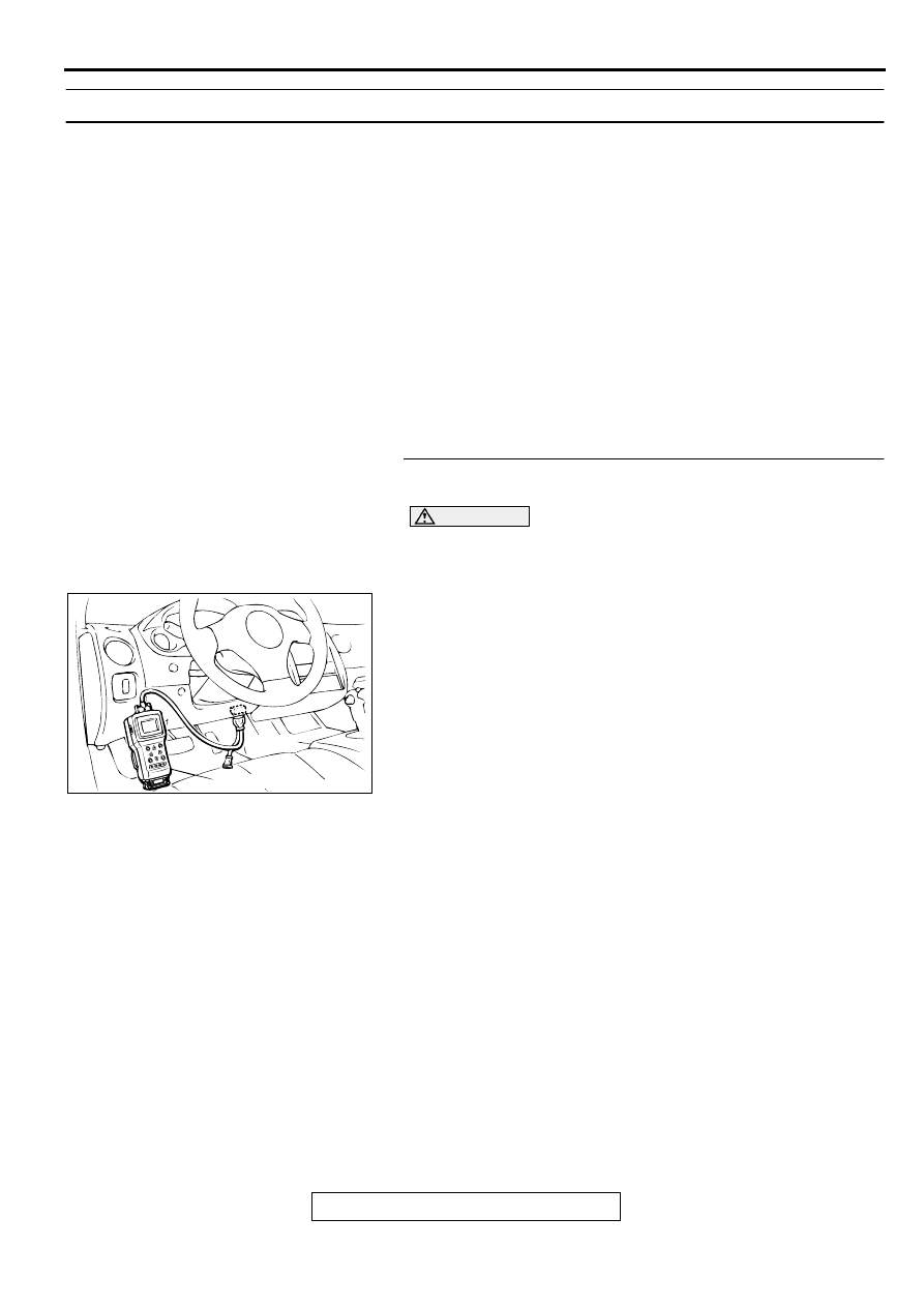
STEP 1. Using scan tool MB991502, check data list item 15:
A/T Fluid Temperature Sensor.
CAUTION
To prevent damage to scan tool MB991502, always turn the
ignition switch to "LOCK" (OFF) position before
connecting or disconnecting scan tool MB991502.
(1) Connect scan tool MB991502 to the data link connector.
(2) Start the engine.
(3) Set scan tool MB991502 to data reading mode for item 15:
A/T Fluid Temperature Sensor.
•
At cool condition: Almost equal to the ambient
temperature (atmospheric temperature)
•
At warm condition: 70 to 80
°
C (158
°
F to 176
°
F)
(4) Turn the ignition switch to "LOCK" (OFF) position.
Q: Is the sensor operating properly?
YES : This malfunction is intermittent. Refer to GROUP 00,
How to Use Troubleshooting/Inspection Service
Points
−
How to Cope with Intermittent Malfunction
NO : Go to Step 2.
AC001252
MB991502
16 PIN
AB
AUTOMATIC TRANSAXLE DIAGNOSIS
TSB Revision
AUTOMATIC TRANSAXLE
23A-82
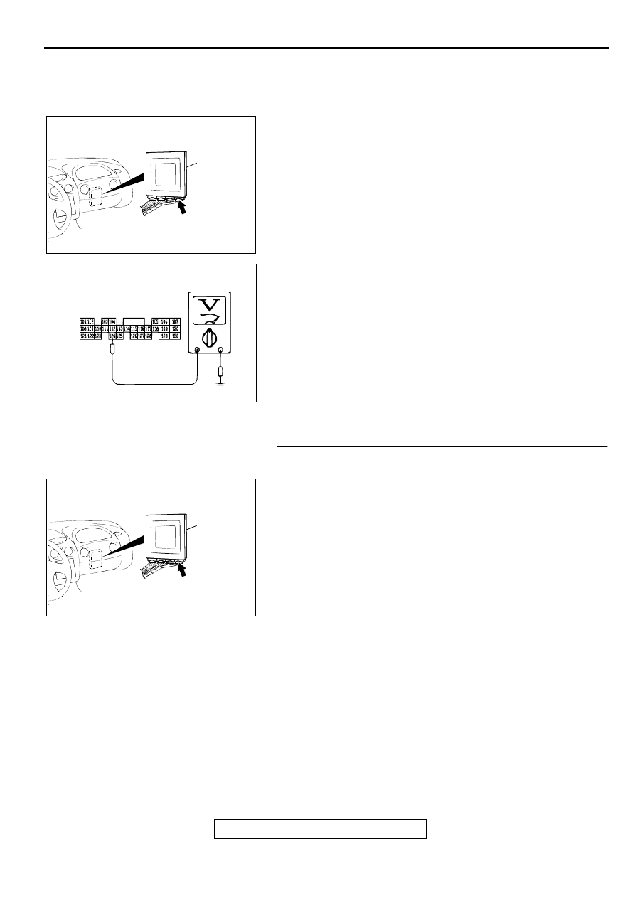
STEP 2. Check the sensor output voltage at PCM
connector C-61 <2.4L Engine> or C-63 <3.0L Engine> by
backprobing.
(1) Do not disconnect connector C-61 <2.4L Engine> or C-63
<3.0L Engine>.
(2) Turn the ignition switch to "ON" position.
(3) Measure the voltage between terminal 124 and ground by
backprobing.
•
When A/T fluid temperature is 20
°
C (68
°
F), voltage
should be between 3.8 and 4.0 volts.
•
When A/T fluid temperature is 40
°
C (104
°
F), voltage
should be between 3.2 and 3.4 volts.
•
When A/T fluid temperature is 80
°
C (176
°
F), voltage
should be between 1.7 and 1.9 volts.
(4) Turn the ignition switch to "LOCK" (OFF) position.
Q: Is the voltage normal?
YES : Go to Step 3.
NO : Go to Step 5.
STEP 3. Check connector C-61 <2.4L Engine> or C-63
<3.0L Engine> at PCM for damage.
Q: Is the connector in good condition?
YES : Go to Step 4.
NO : Repair or replace it. Refer to GROUP 00E, Harness
Connector Inspection
.
AC001657
CONNECTOR: C-61 <2.4L ENGINE> OR
C-63 <3.0L ENGINE>
PCM
AN
AC001792
C-61 <2.4L ENGINE> OR
C-63 <3.0L ENGINE>
CONNECTOR HARNESS
SIDE VIEW
AD
AC001657
CONNECTOR: C-61 <2.4L ENGINE> OR
C-63 <3.0L ENGINE>
PCM
AN
Нет комментариевНе стесняйтесь поделиться с нами вашим ценным мнением.
Текст