Mitsubishi Eclipse / Eclipse Spyder (2000-2002). Service and repair manual — part 453
AUTOMATIC TRANSAXLE DIAGNOSIS
TSB Revision
AUTOMATIC TRANSAXLE
23A-103
CIRCUIT OPERATION
•
A coil built into the input shaft speed sensor
generates 0
⇔
5 volts pulse signal at both ends
of this coil when the input shaft rotates. The pulse
signal frequency increases with a rise in input
shaft speed.
•
Both ends of the coil are connected to the PCM
(terminals 57 and 103) via the input shaft speed
sensor connector (terminals 1 and 2).
•
The PCM detects the input shaft speed by the
signal input to terminal 103.
•
The input shaft speed sensor generates the pulse
signal as the teeth of the underdrive clutch
retainer pass the magnetic tip of the sensor.
DTC SET CONDITIONS
If no output pulse is detected from the input shaft
speed sensor for one second or more while driving in
3rd or 4th gear at a speed of 30 km/h (19 mph) or
more, it is judged to be an open circuit or short circuit
in the input shaft speed sensor and diagnostic
trouble code number "22" is output four times, the
transmission is locked into 3rd gear or 2nd gear as a
fail-safe measure, and the "N" range light flashes
once per second.
TROUBLESHOOTING HINTS (The most likely
causes for this code to be set:)
•
Malfunction of the input shaft speed sensor circuit
•
Malfunction of the underdrive clutch retainer
•
Damaged harness, connector
•
Malfunction of the PCM
DIAGNOSIS
Required Special Tool:
MB991502: Scan Tool (MUT-II)
AC001657
CONNECTORS: C-54 <2.4L ENGINE> OR
C-55 <3.0L ENGINE>, C-61 <2.4L ENGINE>
OR C-63 <3.0L ENGINE>
PCM
AM
C-54 <2.4L ENGINE>
OR
C-55 <3.0L ENGINE>
C-61 <2.4L ENGINE>
OR
C-63 <3.0L ENGINE>
AC001691
CONNECTORS: C-101, C-107
C-101
JUNCTION BLOCK
(FRONT VIEW)
C-107
AN
AUTOMATIC TRANSAXLE DIAGNOSIS
TSB Revision
AUTOMATIC TRANSAXLE
23A-104
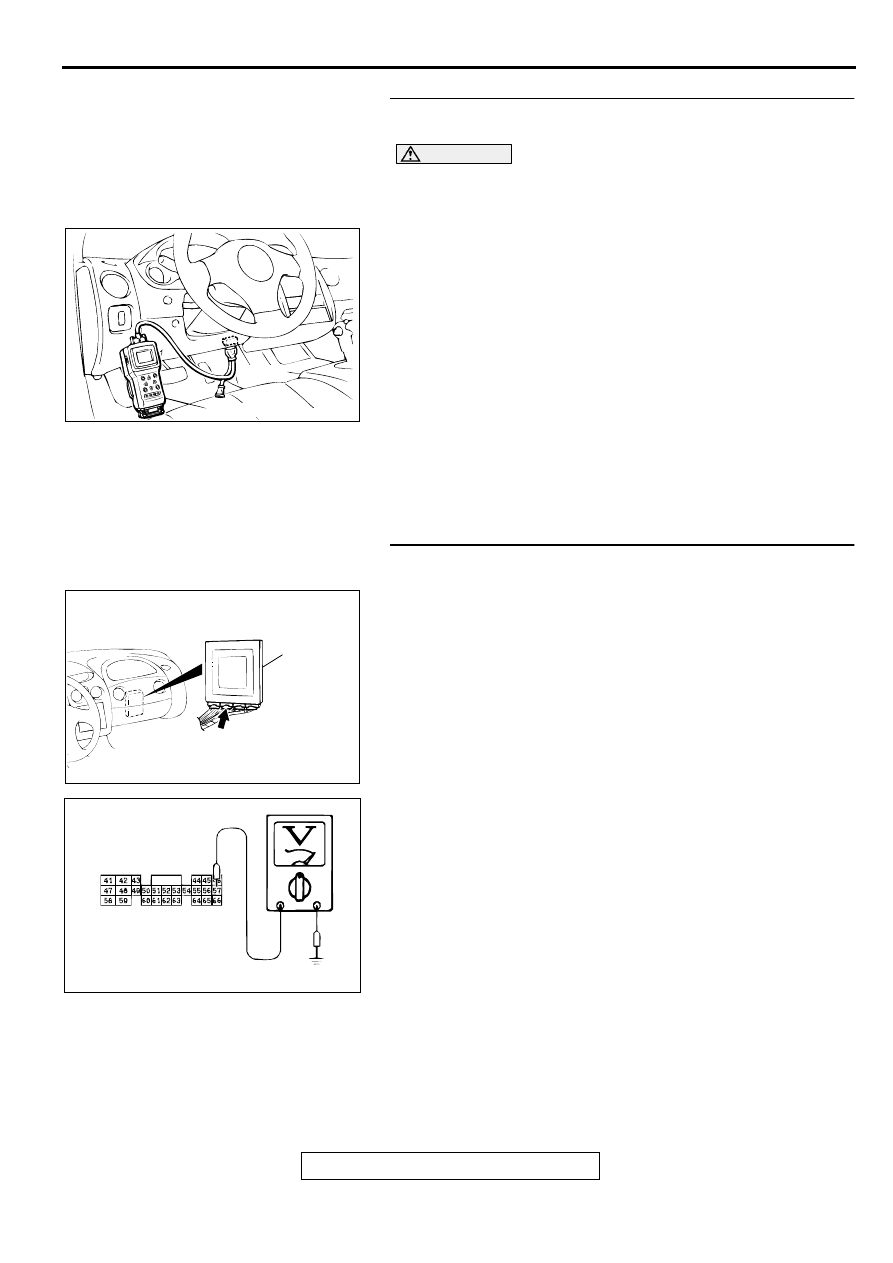
STEP 1. Using scan tool MB991502, check data list item 22:
Input Shaft Speed Sensor.
CAUTION
To prevent damage to scan tool MB991502, always turn the
ignition switch to "LOCK" (OFF) position before
connecting or disconnecting scan tool MB991502.
(1) Connect scan tool MB991502 to the data link connector.
(2) Start the engine.
(3) Set scan tool MB991502 to data reading mode for item 22:
Input Shaft Speed Sensor.
•
When driving at constant speed of 50km/h (31mph), the
display should be "1,600
−
1,900 r/min." <2.4L Engine>,
"1,300
−
1,600 r/min." <3.0L Engine> (Gear range: 3rd
gear)
(4) Turn the ignition switch to "LOCK" (OFF) position.
Q: Is the sensor operating properly?
YES : This malfunction is intermittent. Refer to GROUP 00,
How to Use Troubleshooting/Inspection Service
Points
−
How to Cope with Intermittent Malfunction
NO : Go to Step 2.
STEP 2. Check the ground voltage at PCM connector C-54
<2.4L Engine> or C-55 <3.0L Engine> by backprobing.
(1) Do not disconnect connector C-54 <2.4L Engine> or C-55
<3.0L Engine>.
(2) Turn the ignition switch to "ON" position.
(3) Measure the voltage between terminal 57 and ground by
backprobing.
•
Voltage should be 0.5 volt or less.
(4) Turn the ignition switch to "LOCK" (OFF) position.
Q: Is the voltage normal?
YES : Go to Step 5.
NO : Go to Step 3.
AC001252
MB991502
16 PIN
AB
AC001657
CONNECTOR: C-54 <2.4L ENGINE> OR
C-55 <3.0L ENGINE>
PCM
AL
AC001791
C-54 <2.4L ENGINE> OR
C-55 <3.0L ENGINE>
CONNECTOR HARNESS
SIDE VIEW
AD
AUTOMATIC TRANSAXLE DIAGNOSIS
TSB Revision
AUTOMATIC TRANSAXLE
23A-105
STEP 3. Check connector C-54 <2.4L Engine> or C-55
<3.0L Engine> at PCM for damage.
Q: Is the connector in good condition?
YES : Go to Step 4.
NO : Repair or replace it. Refer to GROUP 00E, Harness
Connector Inspection
.
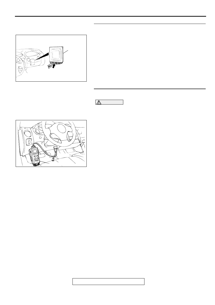
STEP 4. Using scan tool MB991502, check data list item 22:
Input Shaft Speed Sensor.
CAUTION
To prevent damage to scan tool MB991502, always turn the
ignition switch to "LOCK" (OFF) position before
connecting or disconnecting scan tool MB991502.
(1) Connect scan tool MB991502 to the data link connector.
(2) Start the engine.
(3) Set scan tool MB991502 to data reading mode for item 22:
Input Shaft Speed Sensor.
•
When driving at constant speed of 50km/h (31mph), the
display should be "1,600
−
1,900 r/min." <2.4L Engine>,
"1,300
−
1,600 r/min." <3.0L Engine> (Gear range: 3rd
gear)
(4) Turn the ignition switch to "LOCK" (OFF) position.
Q: Is the sensor operating properly?
YES : This malfunction is intermittent. Refer to GROUP 00,
How to Use Troubleshooting/Inspection Service
Points
−
How to Cope with Intermittent Malfunction
NO : Replace the PCM.
AC001657
CONNECTOR: C-54 <2.4L ENGINE> OR
C-55 <3.0L ENGINE>
PCM
AL
AC001252
MB991502
16 PIN
AB
AUTOMATIC TRANSAXLE DIAGNOSIS
TSB Revision
AUTOMATIC TRANSAXLE
23A-106
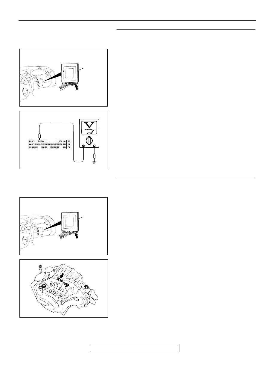
STEP 5. Check the sensor output voltage at PCM
connector C-61 <2.4L Engine> or C-63 <3.0L Engine> by
backprobing.
(1) Do not disconnect connector C-61 <2.4L Engine> or C-63
<3.0L Engine>.
(2) Disconnect connector B-42 at the input shaft speed sensor.
(3) Turn the ignition switch to "ON" position.
(4) Measure the voltage between terminal 103 and ground by
backprobing.
•
Voltage should be between 4.8 and 5.2 volts.
(5) Turn the ignition switch to "LOCK" (OFF) position.
Q: Is the voltage normal?
YES : Go to Step 8.
NO : Go to Step 6.
STEP 6. Check connectors C-61 <2.4L Engine> or C-63
<3.0L Engine> at PCM and B-42 at input shaft speed
sensor for damage.
Q: Are the connectors in good condition?
YES : Go to Step 7.
NO : Repair or replace it. Refer to GROUP 00E, Harness
Connector Inspection
.
AC001657
CONNECTOR: C-61 <2.4L ENGINE> OR
C-63 <3.0L ENGINE>
PCM
AN
AC001810
C-61 <2.4L ENGINE> OR
C-63 <3.0L ENGINE>
CONNECTOR HARNESS
SIDE VIEW
AD
AC001657
CONNECTOR: C-61 <2.4L ENGINE> OR
C-63 <3.0L ENGINE>
PCM
AN
AC001835
CONNECTOR: B-42
AD
Нет комментариевНе стесняйтесь поделиться с нами вашим ценным мнением.
Текст