Mitsubishi Eclipse / Eclipse Spyder (2000-2002). Service and repair manual — part 573
FRONT DISC BRAKE ASSEMBLY
TSB Revision
BASIC BRAKE SYSTEM
35A-41
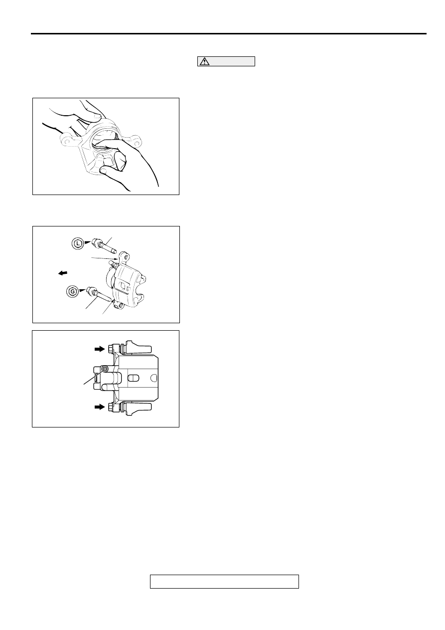
<<B>> PISTON SEAL REMOVAL
CAUTION
Do not use a flat-tipped screwdriver or similar tool to
remove piston seal. These may damage the inner side of
the cylinder.
1. Remove the piston seal with your finger tip.
2. Clean the piston surface and inner cylinder with alcohol or
brake fluid DOT 3 or DOT 4.
ASSEMBLY SERVICE POINTS
>>A<< LOCK PIN/GUIDE PIN INSTALLATION <2.4L
ENGINE>
Install the guide pin as illustrated that each head mark of the
guide pin and the lock pin matches the indication mark ("G" or
"L") located on the caliper body.
>>B<< BUSHING/LOCK PIN/GUIDE PIN INSTALLATION
<3.0L ENGINE>
Install the bushing and lock pin to the bleeder nipple side at the
caliper body, the guide pin to its opposite side, respectively.
INSPECTION
M1351006300099
•
Check the cylinder for wear, damage or rust.
•
Check the piston surface for wear, damage or rust.
•
Check the caliper body or sleeve for wear.
•
Check the pad for damage or adhesion of grease, check the
backing metal for damage.
ACX00689
AC000912 AB
LOCK PIN
"L"
FRONT
GUIDE PIN
"G"
AC003820AB
BUSHING AND
LOCK PIN
BLEEDER
NIPPLE
GUIDE PIN
REAR DISC BRAKE ASSEMBLY
TSB Revision
BASIC BRAKE SYSTEM
35A-42
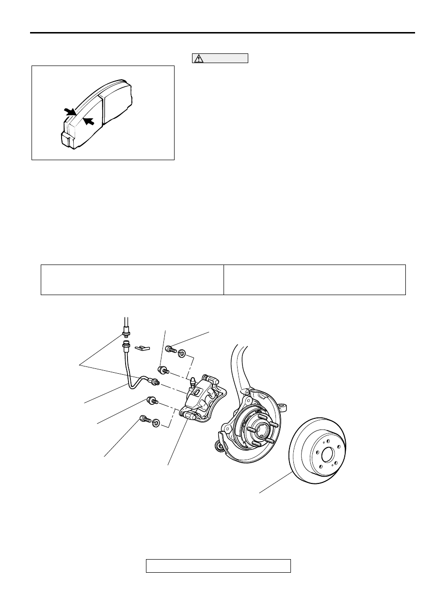
PAD WEAR CHECK
WARNING
•
Always replace both brake pads on each wheel as
a set (both front wheels or both rear wheels).
Failure to do so will result in uneven braking,
which may cause unreliable brake operation.
•
If there is significant difference in the thickness of
the pads on the left and right sides, check the
sliding condition of the piston, lock pin and guide
pin.
Measure thickness at the thinnest and most worn area of the
pad.
Replace the pad assembly if pad thickness is less than the limit
value.
Standard value: 10 mm (0.39 inch)
Minimum limit: 2.0 mm (0.08 inch)
R EAR D ISC B R A K E A SSEM BLY
REMOVAL AND INSTALLATION
M1351007000068
Required Special Tool:
•
MB990520: Disc Brake Piston Expander
ACX00690
Pre-removal Operation
•
Brake Fluid Draining
Post-installation Operation
•
Brake Fluid Supplying
•
Brake Line Bleeding (Refer to
.)
AC002002 AB
60 ± 5 N·m
44 ± 3 ft-lb
60 ± 5 N·m
44 ± 3 ft-lb
55 ± 5 N·m
41 ± 3 ft-lb
55 ± 5 N·m
41 ± 3 ft-lb
15 ± 2 N·m
11 ± 1 ft-lb
1
2
3
REMOVAL STEPS
1. BRAKE HOSE
>>A<<
2. REAR BRAKE ASSEMBLY
3. BRAKE DISC
REAR DISC BRAKE ASSEMBLY
TSB Revision
BASIC BRAKE SYSTEM
35A-43
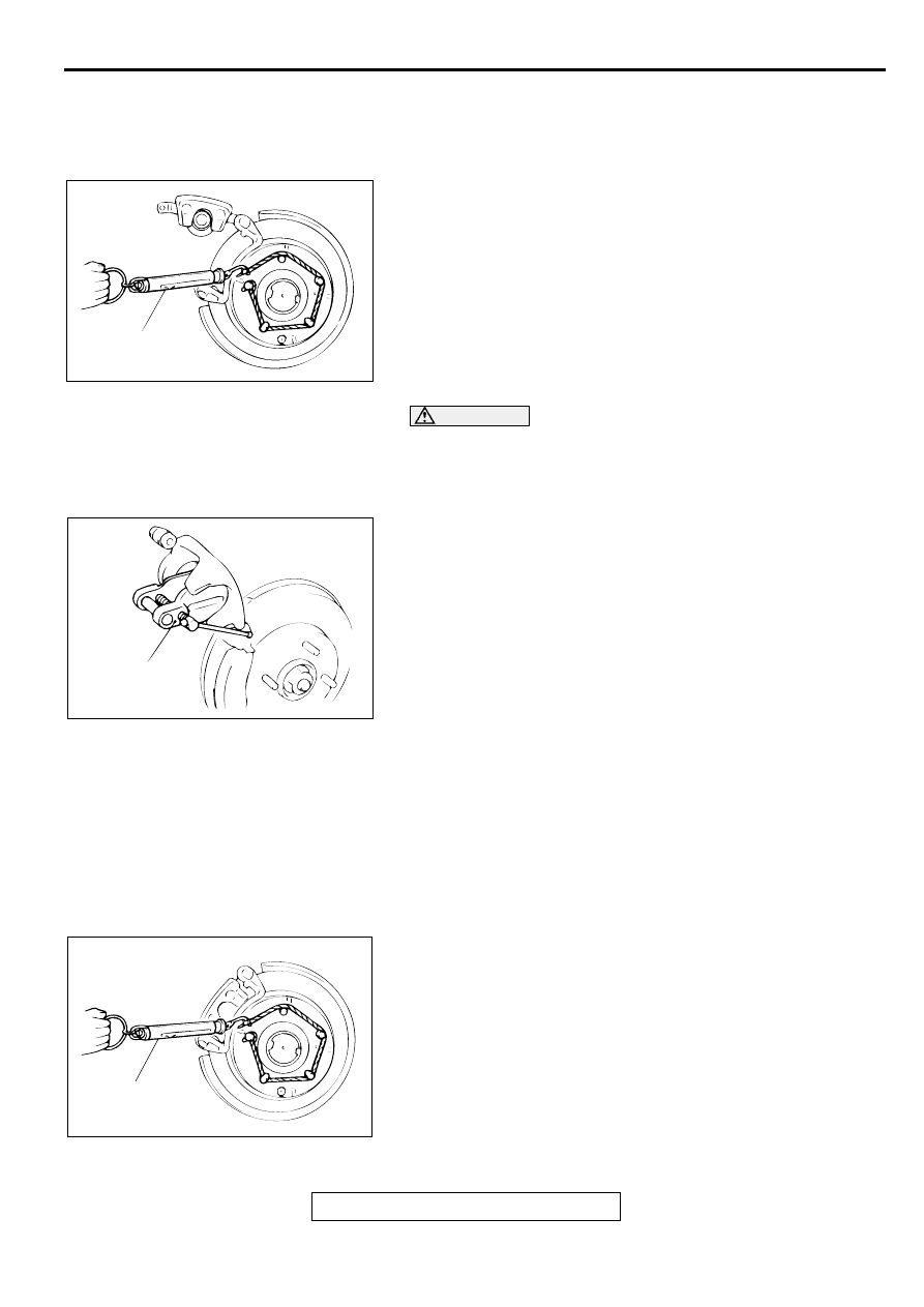
INSTALLATION SERVICE POINT
>>A<< REAR BRAKE ASSEMBLY INSTALLATION
1. In order to measure brake drag torque after pad installation,
measure hub torque with the pads removed.
2. Use a spring scale to measure hub torque in the direction
shown. Record the value.
CAUTION
Do not let any oil, grease or other contamination get onto
the friction surfaces of the pads and brake discs.
3. After re-installing the caliper support, install the pad clips
and pads to the caliper support.
4. Clean the piston and insert it into the cylinder with special
tool MB990520.
5. Be careful that the piston boot does not become caught,
when lowering the caliper assembly and installing the guide
pin.
6. Check brake drag force as follows:
(1) Start the engine and hold the brake pedal down for five
seconds. [Pedal depression force: approximately 196 N
(44 pound)]
(2) Stop the engine.
(3) Turn the brake disc forward ten times.
(4) Use a spring scale to measure the hub torque with pads
installed in the same direction as earlier.
(5) Calculate the drag force of the disc brake [difference
between hub torque with pads installed and hub torque
with pads removed].
Standard value: 69 N (16 pound) or less
7. If the drag torque exceeds the standard value, disassemble
and clean the piston. Check for corrosion or worn piston
seal, and check the sliding condition of the lock pin and
guide pin.
AC000917AB
SPRING
SCALE
AC000918
MB990520
AB
AC000919
SPRING
SCALE
AB
REAR DISC BRAKE ASSEMBLY
TSB Revision
BASIC BRAKE SYSTEM
35A-44
INSPECTION
M1351007100076
BRAKE DISC CHECK
Disc wear (Refer to
.)
Disc run-out (Refer to
.)
Disc inside diameter (Refer to
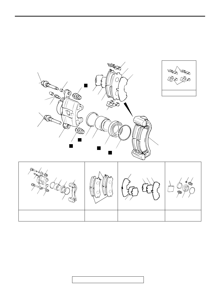
DISASSEMBLY AND ASSEMBLY
M1351007200062
AC000920
BRAKE CALIPER KIT
PAD SET
SHIM KIT
SEAL AND BOOT
REPAIR KIT
AB
17
17
CLIP KIT
17
15
16
13
14
12
17
5
N
3
2
11
1
7.9 ± 0.9 N·m
70 ± 8 in-lb
43 ± 6 N·m
32 ± 4 ft-lb
43 ± 6 N·m
32 ± 4 ft-lb
10
5
N
N
9
8
N
7
6
N
4
2
3 5
9 8
7
4
11
1
10
5
6
12
15
16
1314 16
1413
9
3 5
5 7 6
GREASE
CALIPER ASSEMBLY
DISASSEMBLY STEPS
>>A<<
1. GUIDE PIN
>>A<<
2. LOCK PIN
3. BUSHING
4. CALIPER SUPPORT, PAD, CLIP
AND SHIM ASSEMBLY
5. BOOT
6. BOOT RING
<<A>>
7. PISTON BOOT
<<A>>
8. PISTON
<<B>>
9. PISTON SEAL
10. CALIPER BODY
11. BLEEDER SCREW
PAD ASSEMBLY DISASSEMBLY
STEPS
>>A<<
1. GUIDE PIN
>>A<<
2. LOCK PIN
CALIPER ASSEMBLY
DISASSEMBLY STEPS (Continued)
Нет комментариевНе стесняйтесь поделиться с нами вашим ценным мнением.
Текст