Mitsubishi Eclipse / Eclipse Spyder (2000-2002). Service and repair manual — part 513
ON-VEHICLE SERVICE
TSB Revision
AUTOMATIC TRANSAXLE
23A-344
(4) Loosen the locking nut of the key interlock cable.
(5) Push the cable joint on the lock cam gently toward the
arrow until the cable stops. Tighten the locking nut.
(6) Install the floor console.
3. After adjusting, check the operation once more. If the
operation is still incorrect, replace the key interlock cable.
(Refer to
.)
SHIFT LOCK MECHANISM CHECK
M1232001000064
1. Carry out the following inspections.
2. When the above operations are defective, adjust the shift
lock cable as follows:
(1) Remove the floor console. (Refer to GROUP 54A - Floor
console
.)
(2) Shift selector lever to "P."
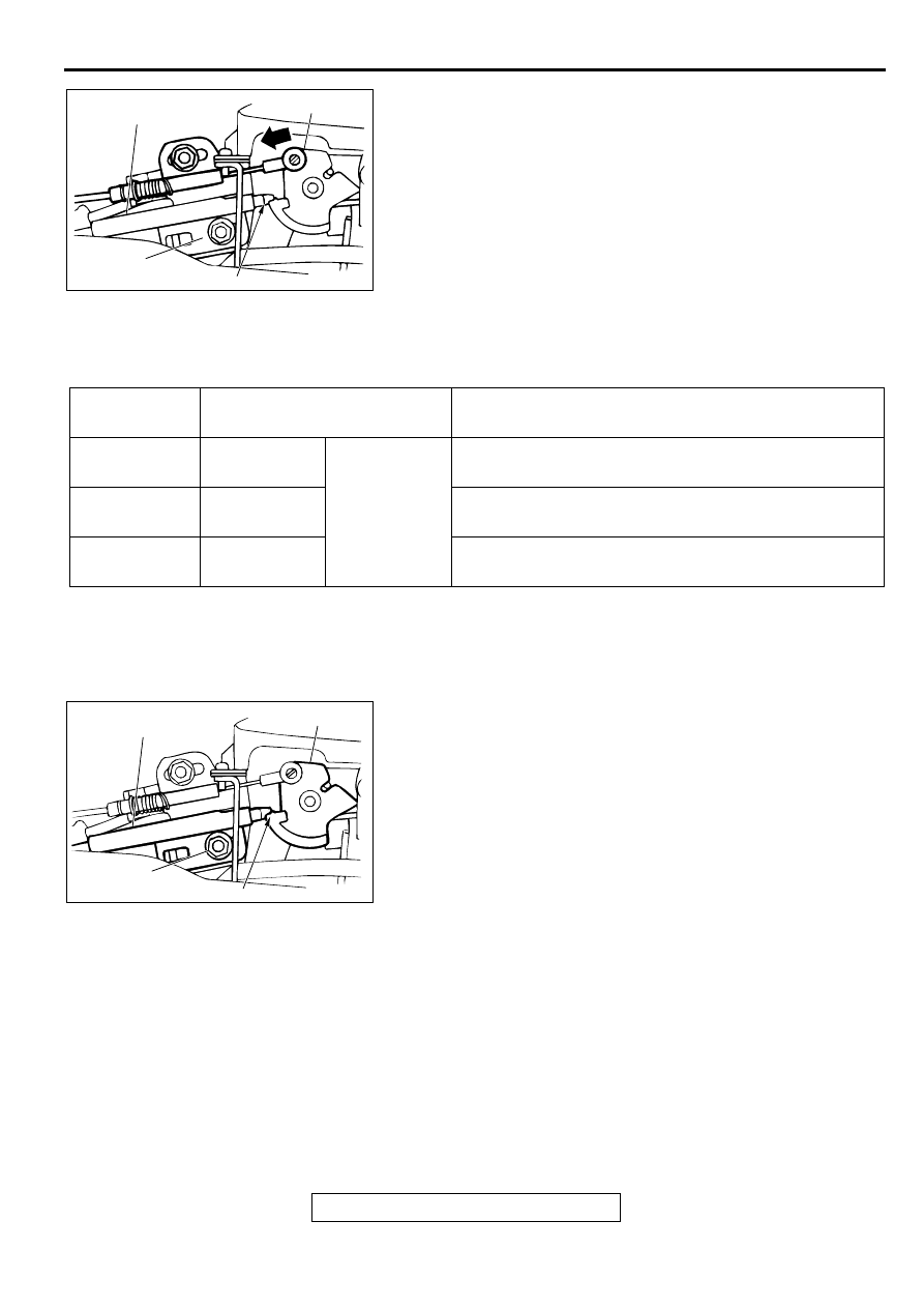
(3) Loosen the locking nut of shift lock cable.
(4) Tighten the locking nut so that the end of the shift lock
cable comes above the red marking of the lock cam.
(5) Install the floor console.
3. After adjusting, check the operation once more. If the
operation is still incorrect, replace the shift lock cable. (Refer
to
AC0001627AB
RED MARKING
LOCKING
NUT
SHIFT LOCK CABLE
LOCK CAM
INSPECTION
PROCEDURE
INSPECTION CONTENTS
CHECK DETAILS (NORMAL CONDITION)
1
Brake pedal:
Not depressed
Ignition key
position: "ACC"
Push in the selector lever push button. Shifting from "P"
to other positions is not possible.
2
Brake pedal:
Depressed
Push in the selector lever push button. Shifting from "P"
to other positions smoothly is possible.
3
Brake pedal:
Not depressed
Push in the selector lever push button. Shifting from "R"
to "P" smoothly is possible.
AC001628AB
RED MARKING
LOCKING
NUT
LOCK CAM
SHIFT LOCK CABLE
TRANSAXLE CONTROL
TSB Revision
AUTOMATIC TRANSAXLE
23A-345
TR A N SA XLE C O N TR O L
REMOVAL AND INSTALLATION
M1231006600068
CAUTION
When removing and installing the transmission control cable and shift lock cable unit, be careful not
to impact the SRS-ECU.
Pre-removal and Post-installation Operation
•
Air Cleaner Assembly Removal and Installation (Refer to
GROUP 15
•
Battery and Battery Tray Removal and Installation (Refer
to GROUP 54A
•
Front Driver's Side Under Cover Removal and Installation
(Refer to GROUP 52A, Instrument Panel
•
Floor Console Box Removal and Installation (Refer to
GROUP 52A, Floor console
.)
AC001630AB
1
2
4
5
12 ± 2 N·m
102 ± 22 in-lb
3
10
12 ± 2 N·m
102 ± 22 in-lb
8
12 ± 2 N·m
102 ± 22 N·m
7
6
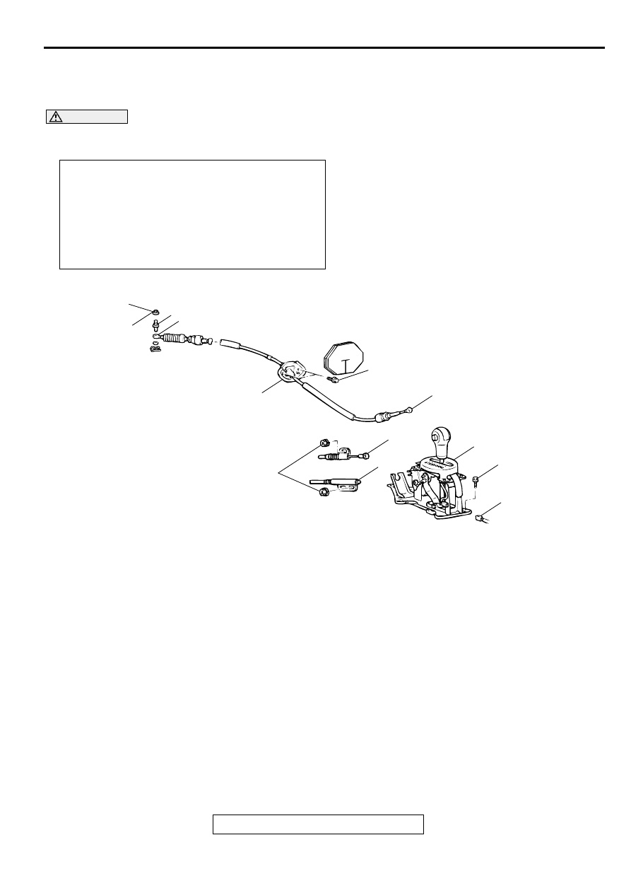
<VEHICLES WITHOUT SPORT MODE>
12 ± 2 N·m
102 ± 22 N·m
TRANSAXLE CONTROL
TSB Revision
AUTOMATIC TRANSAXLE
23A-346
INSTALLATION SERVICE POINT
>>A<< SHIFT LOCK CABLE (SELECTOR LEVER SIDE)
INSTALLATION
1. Place the selector lever in position "P."
2. Fasten the shift lock cable at the position where the end of
the shift lock cable is positioned above the red marking.
AC001631AB
1
2
4
5
12 ± 2 N·m
102 ± 22 in-lb
3
10
12 ± 2 N·m
102 ± 22 in-lb
9
12 ± 2 N·m
102 ± 22 N·m
7
6
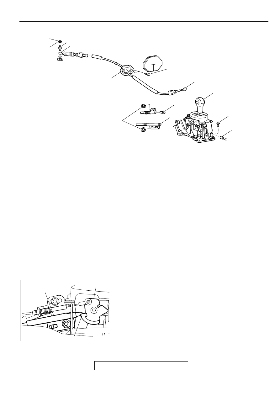
<VEHICLES WITH SPORT MODE>
12 ± 2 N·m
102 ± 22 N·m
TRANSAXLE CONTROL CABLE
ASSEMBLY REMOVAL STEPS
>>C<<
1.
NUT
2.
ADJUSTER
3.
TRANSAXLE CONTROL CABLE
ASSEMBLY CONNECTION
(SELECTOR LEVER ASSEMBLY
SIDE)
4.
TRANSAXLE CONTROL CABLE
ASSEMBLY (TRANSAXLE SIDE)
•
HEATER/COOLER UNIT (REFER
TO GROUP 55, HEATER/COOLER
UNIT, HEATER CORE AND
EVAPORATOR
5.
TRANSAXLE CONTROL CABLE
ASSEMBLY
SELECTOR LEVER ASSEMBLY
REMOVAL STEPS
3.
TRANSAXLE CONTROL CABLE
ASSEMBLY CONNECTION
(SELECTOR LEVER ASSEMBLY
SIDE)
>>B<<
6.
KEY INTERLOCK CABLE
CONNECTION (SELECTOR
LEVER SIDE)
>>A<<
7.
SHIFT LACK CABLE
CONNECTION (SELECTOR
LEVER SIDE)
8.
A/T SELECTOR LEVER POSITION
ILLUMINATION LIGHT
CONNECTOR
9.
HARNESS CONNECTOR
10. SELECTOR LEVER ASSEMBLY
AC001628AC
RED MARKING
SHIFT LOCK CABLE
LOCK CAM
TRANSAXLE CONTROL
TSB Revision
AUTOMATIC TRANSAXLE
23A-347
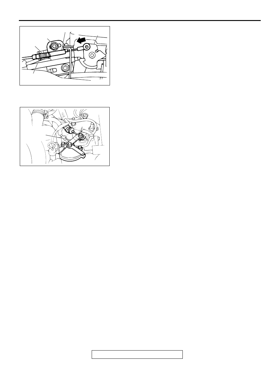
>>B<< KEY INTERLOCK CABLE (SELECTOR LEVER SIDE)
INSTALLATION
1. Install the key interlock cable on the lock cam.
2. Install the spring and washer of the key interlock cable as
shown.
3. While lightly pushing the cable coupling portion of the lock
cam in the direction A, tighten the nut to the specified
torque.
Tightening torque: 12
±
2 N
⋅
m (102
±
22 in-lb)
>>C<< NUT INSTALLATION
1. Put the selector lever in the "N" position.
2. Loosen the nut. Gently pull the transaxle control cable in the
direction of the arrow until the cable is taut. Tighten the nut
at the specified torque.
Tightening torque: 12
±
2 N
⋅
m (102
±
22 in-lb)
INSPECTION
M1231006700054
Check the cable assembly for function and for damage.
AC0001627AC
SPRING
WASHER
LOCKING NUT
LOCK CAM
KEY INTERLOCK CABLE
A
AC001632AB
MANUAL
CONTROL
LEVER
NUT
Нет комментариевНе стесняйтесь поделиться с нами вашим ценным мнением.
Текст