Mitsubishi Eclipse / Eclipse Spyder (2000-2002). Service and repair manual — part 691
55-1
GROUP 55
CONTENTS
GENERAL INFORMATION . . . . . . . .
MANUAL A/C DIAGNOSIS . . . . . . . .
INTRODUCTION TO MANUAL A/C
DIAGNOSIS . . . . . . . . . . . . . . . . . . . . . . . .
MANUAL A/C DIAGNOSTIC
TROUBLESHOOTING STRATEGY . . . . . .
SYMPTOM CHART. . . . . . . . . . . . . . . . . . .
SYMPTOM PROCEDURES . . . . . . . . . . . .
CHECK AT ECU TERMINAL . . . . . . . . . . .
TROUBLESHOOTING HINT. . . . . . . . . . . .
SPECIAL TOOLS. . . . . . . . . . . . . . . .
ON-VEHICLE SERVICE. . . . . . . . . . .
REFRIGERANT LEVEL TEST . . . . . . . . . .
MAGNETIC CLUTCH TEST . . . . . . . . . . . .
RECEIVER DRIER TEST . . . . . . . . . . . . . .
PRESSURE SWITCH CHECK . . . . . . . . . .
COMPRESSOR DRIVE BELT
ADJUSTMENT . . . . . . . . . . . . . . . . . . . . . .
CHARGING . . . . . . . . . . . . . . . . . . . . . . . .
PERFORMANCE TEST . . . . . . . . . . . . . . .
REFRIGERANT LEAK REPAIR
PROCEDURE . . . . . . . . . . . . . . . . . . . . . . .
COMPRESSOR NOISE CHECK . . . . . . . .
POWER RELAY CHECK . . . . . . . . . . . . . .
IDLE-UP OPERATION CHECK . . . . . . . . .
HEATER CONTROL ASSEMBLY AND
A/C SWITCH . . . . . . . . . . . . . . . . . . . .
REMOVAL AND INSTALLATION . . . . . . . .
INSPECTION. . . . . . . . . . . . . . . . . . . . . . . .
HEATER UNIT, HEATER CORE, BLOWER
ASSEMBLY, EVAPORATOR UNIT . .
REMOVAL AND INSTALLATION . . . . . . . .
BLOWER ASSEMBLY AND
RESISTOR . . . . . . . . . . . . . . . . . . . . .
REMOVAL AND INSTALLATION . . . . . . . .
INSPECTION. . . . . . . . . . . . . . . . . . . . . . . .
COMPRESSOR ASSEMBLY AND TENSION
PULLEY . . . . . . . . . . . . . . . . . . . . . . .
REMOVAL AND INSTALLATION . . . . . . . .
INSPECTION. . . . . . . . . . . . . . . . . . . . . . . .
COMPRESSOR MAGNETIC CLUTCH
OPERATION INSPECTION . . . . . . . . . . . .
REVOLUTION PICK-UP SENSOR CHECK
MAGNETIC CLUTCH . . . . . . . . . . . . . . . . .
CONDENSER AND CONDENSER FAN
MOTOR . . . . . . . . . . . . . . . . . . . . . . . .
REMOVAL AND INSTALLATION . . . . . . . .
INSPECTION. . . . . . . . . . . . . . . . . . . . . . . .
REFRIGERANT LINE . . . . . . . . . . . . .
REMOVAL AND INSTALLATION . . . . . . . .
VENTILATORS . . . . . . . . . . . . . . . . . .
REMOVAL AND INSTALLATION . . . . . . . .
55-2
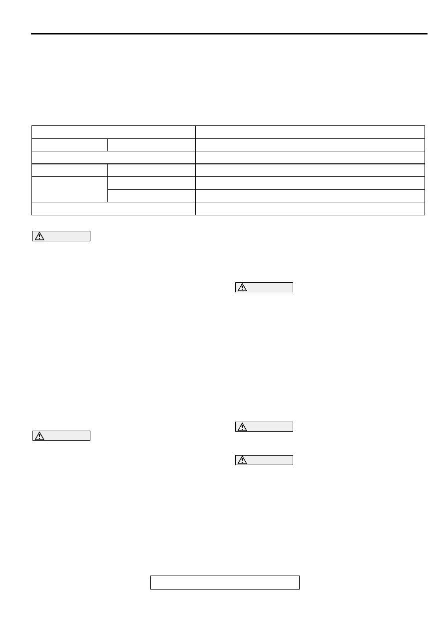
SPECIFICATIONS . . . . . . . . . . . . . . .
FASTENER TIGHTENING
SPECIFICATIONS . . . . . . . . . . . . . . . . . . .
GENERAL SPECIFICATIONS . . . . . . . . . .
SERVICE SPECIFICATIONS . . . . . . . . . . .
GENERAL INFORMATION
TSB Revision
HEATING AND AIR CONDITIONING
55-3
.
G EN ER A L IN FO R M ATIO N
M1552000100050
The heater system uses a two-way-flow full-air-mix
system that features high performance and low
operating noise. It includes an independent face air
blowing function. In addition, an air purifier has been
included.
SAFETY PRECAUTIONS
WARNING
Wear safety goggles and gloves when
servicing the refrigeration system to prevent
severe damage to eyes and hands.
Because R-134a refrigerant is a hydro fluorocarbon
(HFC) which contains hydrogen atoms in place of
chlorine atoms, it will not cause damage to the ozone
layer.
Ozone filters out harmful radiation from the sun. To
assist in protecting the ozone layer, Mitsubishi
Motors Corporation recommends an R-134a
refrigerant recycling device.
Refrigerant R-134a is transparent and colorless in
both the liquid and vapor state. Since it has a boiling
point of
−
29.8
°
C (
−
21.64
°
F) at atmospheric pressure,
it will be a vapor at all normal temperatures and
pressures. The vapor is heavier than air, non-
flammable, and non-explosive. The following
precautions must be observed when handling R-
134a.
WARNING
Do not heat R-134a above 40
°
C (104.0
°
F) or it
may catch fire and explode.
R-134a evaporates so rapidly at normal atmospheric
pressures and temperatures that it tends to freeze
anything it contacts. For this reason, extreme care
must be taken to prevent any liquid refrigerant from
contacting the skin and especially the eyes. Always
wear safety goggles when servicing the refrigeration
part of the A/C system. Keep a bottle of sterile
mineral oil handy when working on the refrigeration
system.
1. Should any liquid refrigerant get into the eyes, use
a few drops of mineral oil to wash them out. R-
134a is rapidly absorbed by the oil.
2. Next splash the eyes with plenty of cold water.
3. Call your doctor immediately even though
irritation has ceased after treatment.
CAUTION
Keep R-134a containers upright when charging
the system.
In most instances, moderate heat is required to bring
the pressure of the refrigerant in its container above
the pressure of the system when charging or adding
refrigerant.
A bucket or large pan of hot water not over 40
°
C
(104.0
°
F) is all the heat required for this purpose. Do
not heat the refrigerant container with a blow torch or
any other means that would raise temperature and
pressure above this temperature. Do not weld or
steam clean on or near the system components or
refrigerant lines.
WARNING
The leak detector for R-134a should be used
to check for refrigerant gas leaks.
CAUTION
Do not allow liquid refrigerant to touch bright
metal or it will be stained.
When metering R-134a into the refrigeration system
keep the supply tank or cans in an upright position. If
the refrigerant container is on its side or upside
down, liquid refrigerant will enter the system and
damage the compressor.
Refrigerant will tarnish bright metal and chrome
surfaces, and in combination with moisture can
severely corrode all metal surfaces.
Items
Specifications
Heater unit
Type
Two-way-flow full-air-mix system
Heater control assembly
Dial type
Compressor
Model
Scroll type <MSC90C>
Dual pressure
switch kPa (psi)
High-pressure switch
ON
→
OFF: 2,942 (426.7), OFF
→
ON: 2,354 (341.4)
Low-pressure switch
ON
→
OFF: 196 (28.4), OFF
→
ON: 221 (32.1)
Refrigerant and quantity g (oz)
R-134a (HFC-134a), Approximately 415
−
435 (14.6
−
15.3)
MANUAL A/C DIAGNOSIS
TSB Revision
HEATING AND AIR CONDITIONING
55-4
OPERATION
Condenser fan and radiator fan control
•
For the operation of each fan, refer to GROUP
14, Diagnosis - Symptom Chart
.
Compressor control
When operating the air conditioning switch
•
The air thermo sensor, which senses the
temperature of the air flowing out of the
evaporator, deactivates the compressor at 5
°
C
(41.0
°
F) or below.
•
The dual pressure switch turns OFF when the
refrigerant pressure becomes excessively high or
low, thus protecting the compressor circuit. (See
Table below.)
•
When the air thermo sensor is activated, the dual
pressure switch is ON, and the ignition switch,
blower switch, and air conditioning switch are
ON, the A/C compressor relay is energized.
When operating the air outlet changeover control
knob
•
When the air outlet changeover control knob is
moved to DEFROSTER or DEFROSTER/FOOT
position, the defroster switch, which is connected
in series to the air conditioning switch, is turned
on. The other compressor control than the above
is the same as that when operating the air
conditioning switch.
When compressor locks <vehicles with 3.0 L
engine>
•
Since the compressor and alternator are driven
by the same belt, the electric generating function
of the alternator also stops when the belt is
broken. In order to assure the electric generating
function of the alternator, there is an A/C-ECU to
prevent breaking of the belt due to slipping when
the compressor locks. The A/C-ECU makes a
comparative calculation of the compressor
revolutions and the engine revolutions which are
detected by the revolution pick-up sensor. When
70% or more slip ratio continues for 3 seconds or
more, the A/C compressor relay goes from on to
off; at the same time, the operation display in the
air conditioner switch blinks to announce an
abnormality.
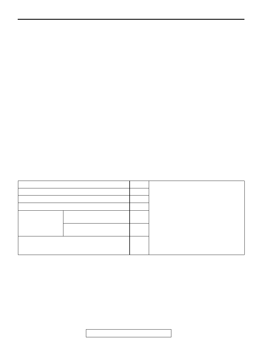
A/C Compressor Relay ON Conditions
M A N U A L A /C D IA G N O S IS
INTRODUCTION TO MANUAL A/C DIAGNOSIS
M1552012200087
With this system, after the outside air or inside air is
taken in through the damper, it is fed to the
evaporator by the blower fan and motor and cooled.
The air cooled by the air mix damper is mixed
appropriately with the warmed air to achieve a
comfortable temperature. If the A/C does not operate
or the cooled air is not discharged, the machine
components or relay may be faulty.
Ignition switch (IG2)
ON
NOTE: . A/C compressor relay is de-
energized when any one switch, sensor or
control unit shown on the left turns off.
NOTE: . The
*
marked device measures the
temperature of the outlet air, and according
to the control characteristics of the magnetic
clutch for the compressor, the automatic
compressor controller outputs the "HI" signal
(12V). When air of 5
°
C (41.0
°
F) or less
blows out of the evaporator, the compressor
magnetic clutch will be turned off.
Blower switch
ON
Air conditioning switch or defroster switch
ON
Air thermo sensor
*
Dual pressure
switch
Low-pressure side 221 kPa
(32.1 psi) or higher
ON
High-pressure side 2,942 kPa
(426.7 psi) or below
ON
A/C compressor relay driving transistor (within
automatic compressor controller and engine control
module <M/T>, powertrain control module <A/T>)
ON
Нет комментариевНе стесняйтесь поделиться с нами вашим ценным мнением.
Текст