Mitsubishi Eclipse / Eclipse Spyder (2000-2002). Service and repair manual — part 549
GENERAL DESCRIPTION
TSB Revision
POWER PLANT MOUNT
32-3
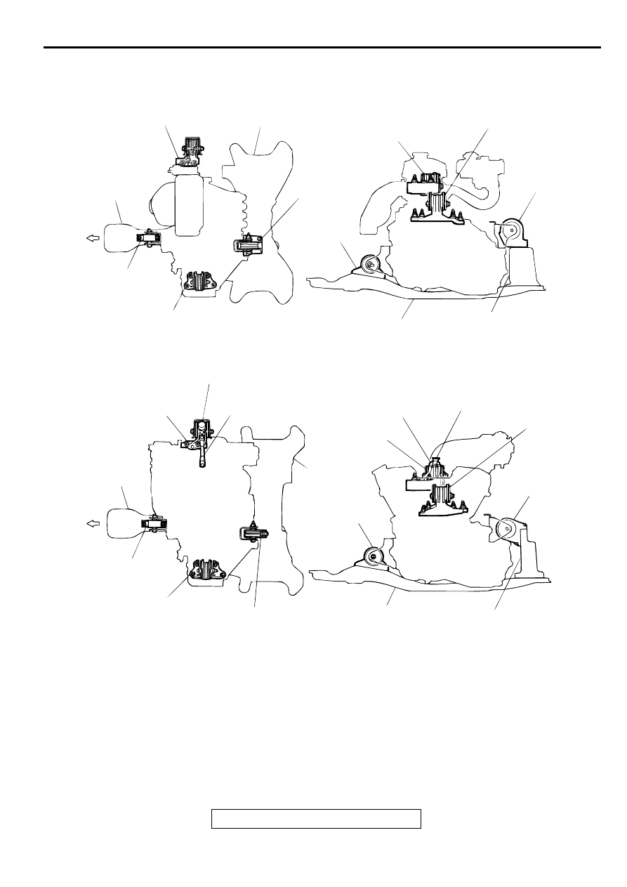
ENGINE MOUNT CONSTRUCTION DIAGRAM
AC000298
FRONT
FRONT
ENGINE MOUNT
ENGINE MOUNT
ENGINE MOUNT
ENGINE MOUNT
CROSSMEMBER
CROSSMEMBER
CROSSMEMBER
CROSSMEMBER
CENTERMEMBER
CENTERMEMBER
CENTERMEMBER
CENTERMEMBER
FRONT ROLL
STOPPER
FRONT ROLL
STOPPER
FRONT ROLL
STOPPER
FRONT ROLL STOPPER
TRANSAXLE MOUNT
TRANSAXLE MOUNT
TRANSAXLE MOUNT
TRANSAXLE
MOUNT
REAR ROLL
STOPPER
REAR ROLL
STOPPER
REAR ROLL
STOPPER
REAR ROLL
STOPPER
DYNAMIC DAMPER
DYNAMIC DAMPER
ENGINE MOUNT STAY
ENGINE
MOUNT
STAY
<2.4L ENGINE>
<3.0L ENGINE>
AB
SPECIAL TOOLS
TSB Revision
POWER PLANT MOUNT
32-4
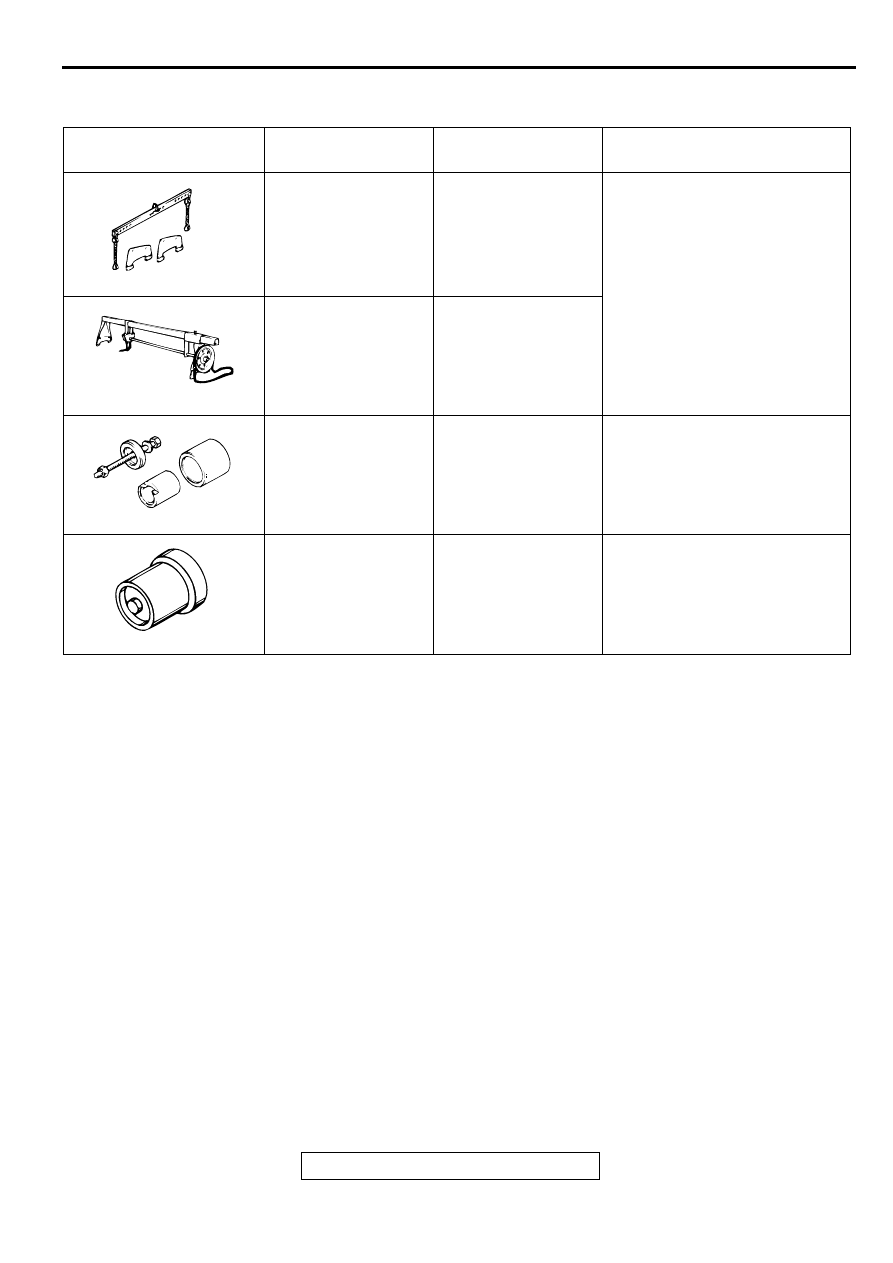
SPECIA L TO O LS
M1321000600066
TOOL
TOOL NUMBER
AND NAME
SUPERSESSION
APPLICATION
MB991453
Engine hanger
Tool not available
To support the engine assembly
during removal and installation
of the transaxle mount
MZ203827
Engine lifter
General service tool
MB991045
Bushing remover and
installer
Tool not available
Driving out and press-fitting of
crossmember bushings A and B
MB990828
Bushing remover and
installer
Tool not available
Driving out and press-fitting of
crossmember bushing C
MB991453
MZ203827
MB991045
MB990828
ENGINE MOUNTING
TSB Revision
POWER PLANT MOUNT
32-5
EN G IN E M O U N TIN G
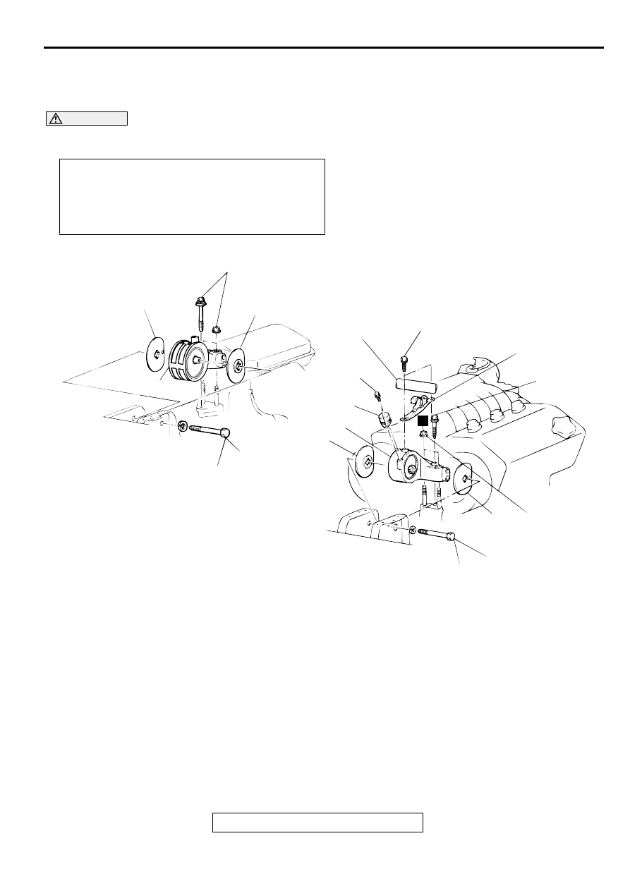
REMOVAL AND INSTALLATION
M1321001100097
CAUTION
Mounting locations marked by
*
should be provisionally tightened, and then fully tightened after
placing the vehicle horizontally and loading the full weight of the engine on the vehicle body.
Pre-removal and Post-installation Operation
•
Jack Up the Engine and Transmission Assembly Until
There is no Weight on the Engine Mount Bracket Insula-
tor.
•
Reserve Tank Removal and Installation (Refer to GROUP
14, Radiator
AC000299
5
5
4
3
1
2
6
4
5
5
81 ± 12 N·m*
60 ± 9 ft-lb*
81 ± 12 N·m*
60 ± 9 ft-lb*
86 ± 12 N·m
64 ± 8 ft-lb
86 ± 12 N·m
64 ± 8 ft-lb
35 ± 6 N·m
26 ± 4 ft-lb
4.9 ± 1.0 N·m
44 ± 8 in-lb
N
AB
<2.4L ENGINE>
<3.0L ENGINE>
3
86 ± 12 N·m
64 ± 8 ft-lb
REMOVAL STEPS
1.
SUCTION HOSE <3.0L ENGINE>
2.
ENGINE MOUNT STAY <3.0L
ENGINE>
3.
ENGINE MOUNT INSULATOR
MOUNTING BOLT
4.
ENGINE MOUNT BRACKET
>>A<<
5.
ENGINE MOUNT STOPPER
6.
DYNAMIC DAMPER <3.0L
ENGINE>
REMOVAL STEPS (Continued)
ENGINE MOUNTING
TSB Revision
POWER PLANT MOUNT
32-6
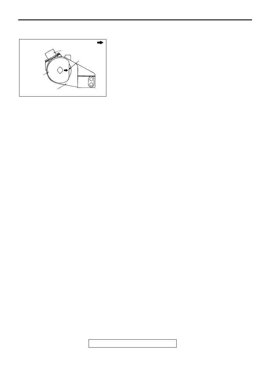
INSTALLATION SERVICE POINT
>>A<< ENGINE MOUNT STOPPER INSTALLATION
Clamp the engine mount stopper so that the arrow points in the
direction as shown in the diagram.
INSPECTION
M1321001200061
•
Check the insulators for cracks, separation or deformation.
•
Check the front insulator stoppers for deformation.
AC000300
ENGINE SIDE
DYNAMIC DAMPER
ARROW
ENGINE
MOUNT
STOPPER
ENGINE MOUNT BRACKET
AB
Нет комментариевНе стесняйтесь поделиться с нами вашим ценным мнением.
Текст