Mitsubishi Eclipse / Eclipse Spyder (2000-2002). Service and repair manual — part 322
MULTIPORT FUEL INJECTION (MFI) DIAGNOSIS
TSB Revision
MULTIPORT FUEL INJECTION (MFI) <3.0L ENGINE>
13B-487
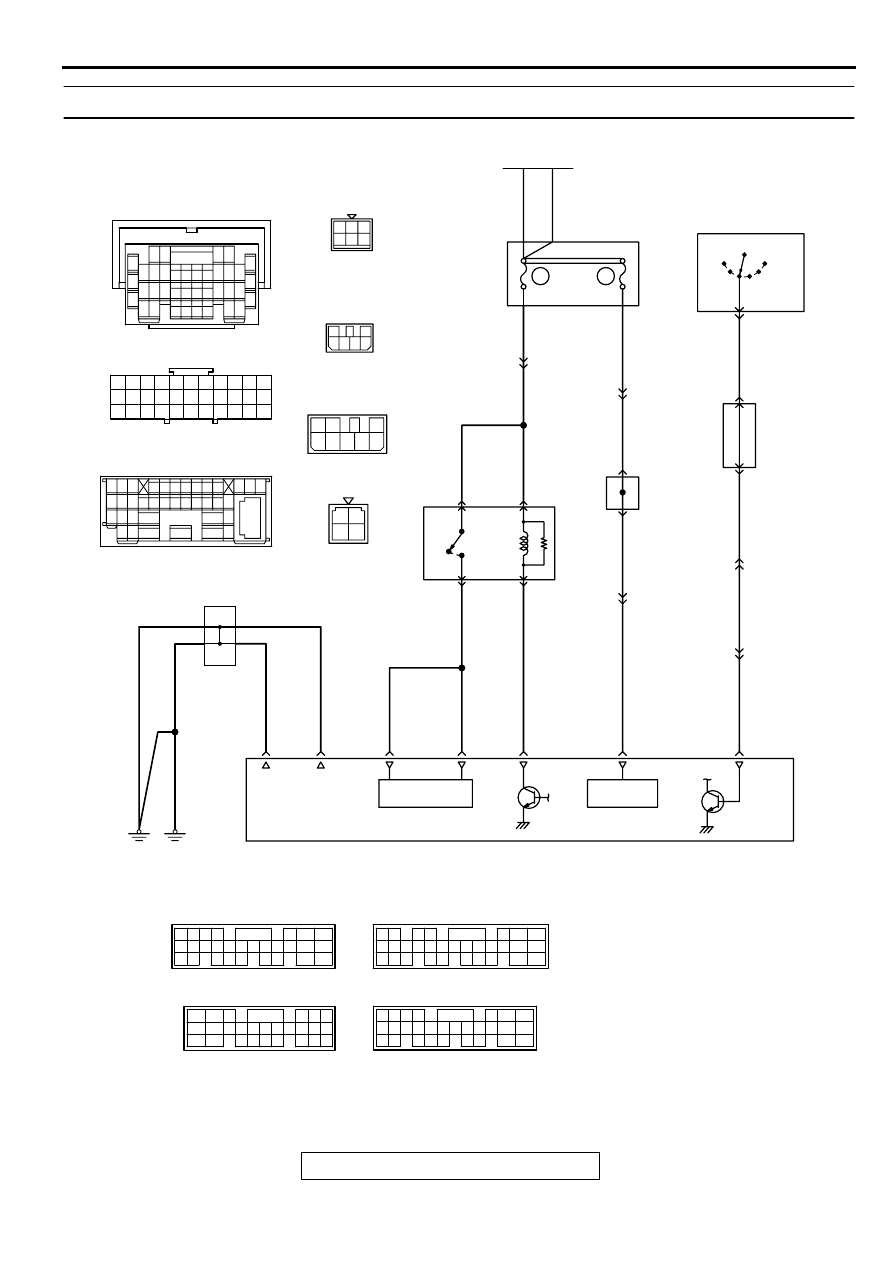
INSPECTION PROCEDURE 29: Power supply system and ignition switch-IG system.
AK000716
4
1 2
3
6
2 3
4 5 6
GREEN
1
1
3
2
4
1
4
8
7
2
6
3
5
5
BLA
CK-
WHITE
BLA
CK-
WHITE
BLA
CK-
WHITE
ORANGE-
BLA
CK
ORANGE-
BLA
CK
ORANGE-
BLA
CK
ORANGE-
BLA
CK
RED
RED
RED
WHITE-VIOLET
RED-
WHITE
RED-
WHITE
BLA
CK
BLA
CK
BLA
CK
BLA
CK
BLA
CK
R
IG2
ST
LOCK
ACC
IG1
C-87
C-87
C-101
MU801331
C-101
IGNITION
SWITCH
2
6
5
JUNCTION
BLOCK
99<M/T>*2
98<A/T>*4
C-07
MU801333
C-07
60<M/T>*1
66<A/T>*3
MFI
RELAY
A-21X
A-21X
3
4
1
2
57<M/T>*1
49<A/T>*3
BATTERY
BACK UP
47<M/T>*1
47<A/T>*3
59<M/T>*1
41<A/T>*3
POWER
SOURCE
58<M/T>*1
48<A/T>*3
46<M/T>*1
42<A/T>*3
ENGINE CONTROL MODULE(ECM)<M/T> OR
POWERTRAIN CONTROL MODULE(PCM)<A/T>
3
29
NOTE
*1:ECM connector C-58<M/T>
*2:ECM connector C-62<M/T>
*3:PCM connector C-55<A/T>
*4:PCM connector C-59<A/T>
65
43
50
42
49
41
48
60 61
64
46 47
58 59
67 68
45
56
66
52
51
44
53
62
54
63
57
55
C-58<M/T>
(MU803782)
C-55<A/T>
(MU803781)
42 43
48 49 50 51 52 53 54 55 56 57
46
45
44
58 59
60 61 62 63
64 65 66
47
41
98
78
71
88 89
76 77
72
79
91
73
80
74
75
81
92
82 83
93
84 85
94
86 87
95 96
90
80
87
81
94
85
82
84
93
86
98
99
74
92
73
83
88
91
95
97
96
100
89
78
71
90
76 77
75
72
79
97
C-62<M/T>
(MU803783)
C-59<A/T>
(MU803782)
15 16
26 27 28 29
32 33 34
17 18 19 20 21 22 23 24 25
30 31
36 37
35
38
10
11 12 13
1 2 3
4 5 6 7 8 9
14
C-89
C-89
C-28
C-78
7 8
5
3 4
35
34
10 11 12
2122 23 24
13 14 15
25 26 27
16
28
17
18 19 20
29
30 31
32 33
36 37
38
9
1 2
6
16
15
18
17
14
20
22
21
9
7
1 2
5
19
3
33
32
30 31
29
28
25
24
23
27
26
6
11
13
4
10
8
12
WHITE
WHITE
BATTERY
DEDICATED
FUSE
13
4
RED-
WHITE
RED-
WHITE
8
C-07
25
C-89
27
C-28
6
9
JOINT
CONNECTOR
C-78
JOINT
GROUND
POINT
MULTIPORT FUEL INJECTION (MFI) DIAGNOSIS
TSB Revision
MULTIPORT FUEL INJECTION (MFI) <3.0L ENGINE>
13B-488
CIRCUIT OPERATION
•
Battery positive voltage is applied to the MFI
relay (terminals 3, 4).
•
When the ignition switch is turned to the "ON"
position, The battery positive voltage is applied to
the ECM (terminal 99) <M/T> or PCM (terminal
98) <A/T>. When the battery positive voltage is
applied, the ECM <M/T> or PCM <A/T> turns the
power transistor in the ECM <M/T> or PCM <A/
T> "ON" and grounds the MFI relay coil. With
this, the MFI relay turns "ON" and the battery
positive voltage is supplied to the ECM (terminal
47, 59) <M/T> or PCM (terminal 41, 47) <A/T>
from the MFI relay (terminal 1).
•
Battery positive voltage is constantly supplied to
the ECM (terminal 60) <M/T> or PCM (terminal
66) <A/T> as the backup power.
AK000225
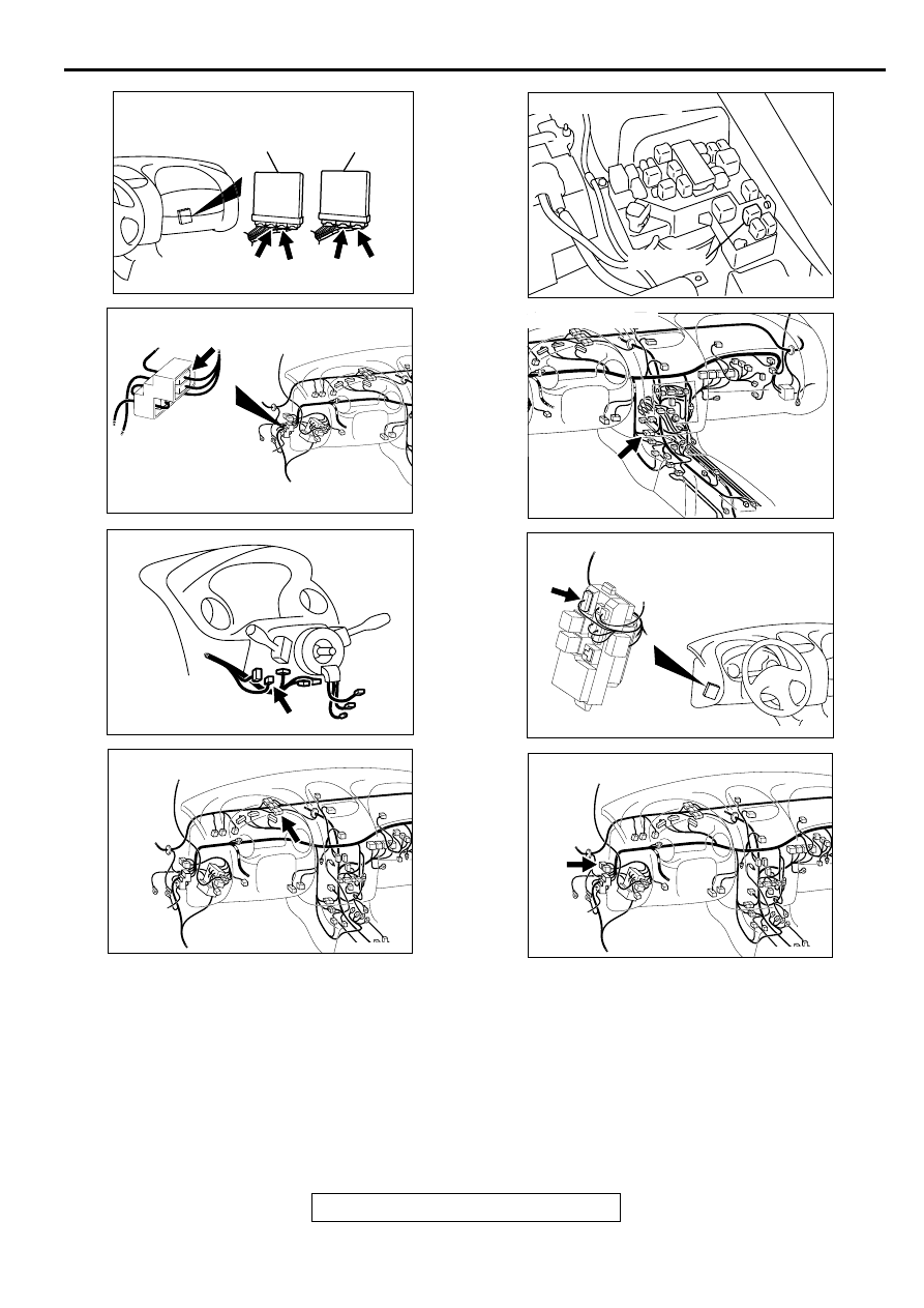
CONNECTORS : C-58, C-62<M/T>,
C-55, C-59<A/T>
C-55
C-58
PCM<A/T>
ECM<M/T>
AK
C-59
C-62
AK000345AE
CONNECTOR:C-89
AK000219
CONNECTOR:C-87
AC
AK000312AJ
CONNECTOR:C-07
AK000226
AK000226AB
CONNECTOR : A-21X
MFI RELAY
AK000733AC
CONNECTOR:C-28
AK000315
CONNECTOR:C-101
AC
AK000312AG
CONNECTOR:C-78
MULTIPORT FUEL INJECTION (MFI) DIAGNOSIS
TSB Revision
MULTIPORT FUEL INJECTION (MFI) <3.0L ENGINE>
13B-489
•
The ECM (terminal 46, 58) <M/T> or PCM
(terminals 42, 48) <A/T> is grounded to the
vehicle body.
TROUBLESHOOTING HINTS (The most likely
causes for this code to be set are:)
•
Malfunction of the ignition switch.
•
Malfunction of the MFI relay.
•
Improper connector contact, open circuit or short-
circuited harness wire.
•
Disconnected ECM <M/T> or PCM <A/T> ground
wire.
•
Malfunction of the ECM <M/T> or PCM <A/T>.
DIAGNOSIS
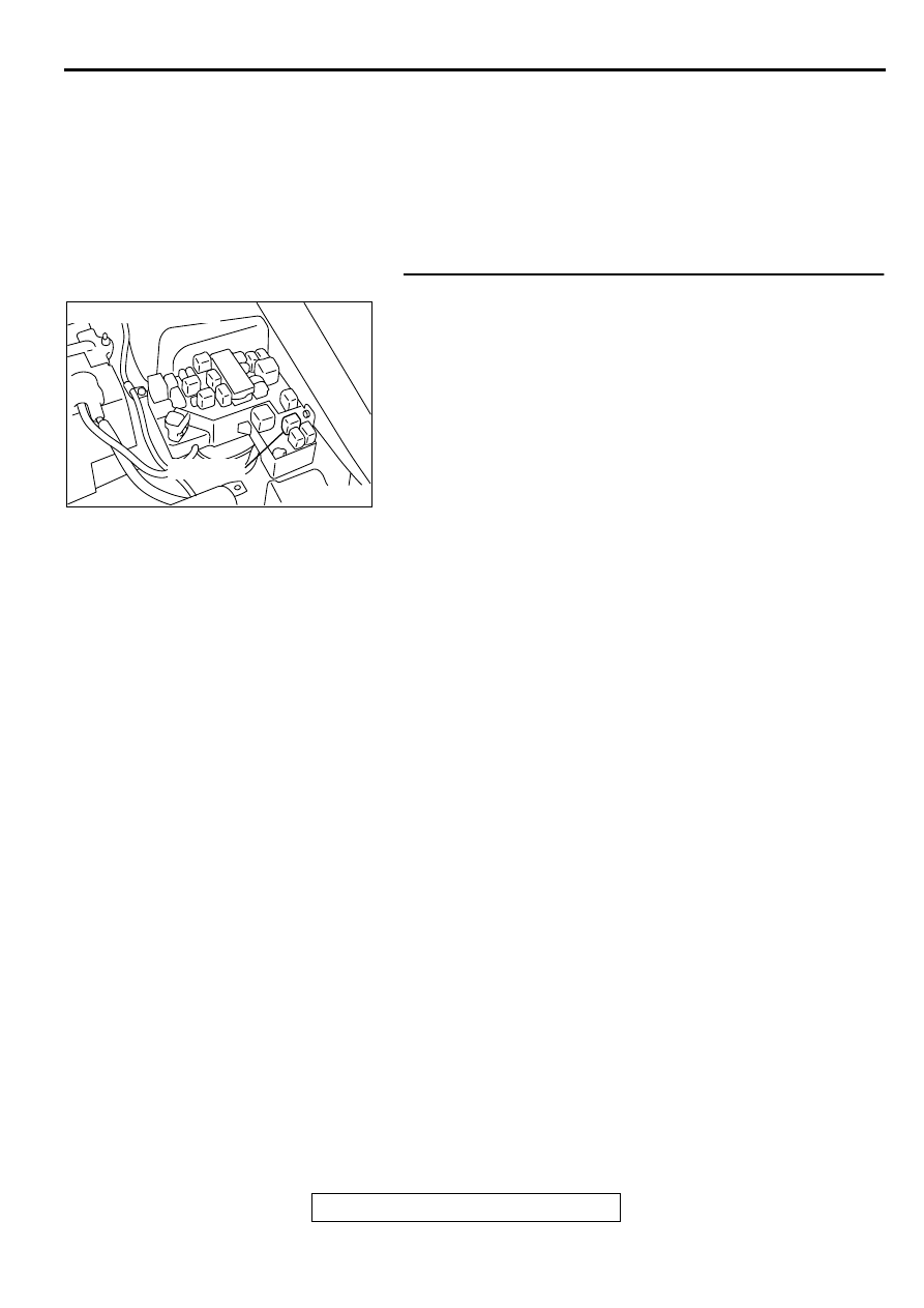
STEP 1. Check connector A-21X at MFI relay for damage.
Q: Is the connector in good condition?
YES : Go to Step 2.
NO : Repair or replace it. Refer to GROUP 00E, Harness
Connector Inspection (
). Then confirm that
the malfunction symptom is eliminated.
AK000226
AK000226AB
CONNECTOR : A-21X
MFI RELAY
MULTIPORT FUEL INJECTION (MFI) DIAGNOSIS
TSB Revision
MULTIPORT FUEL INJECTION (MFI) <3.0L ENGINE>
13B-490
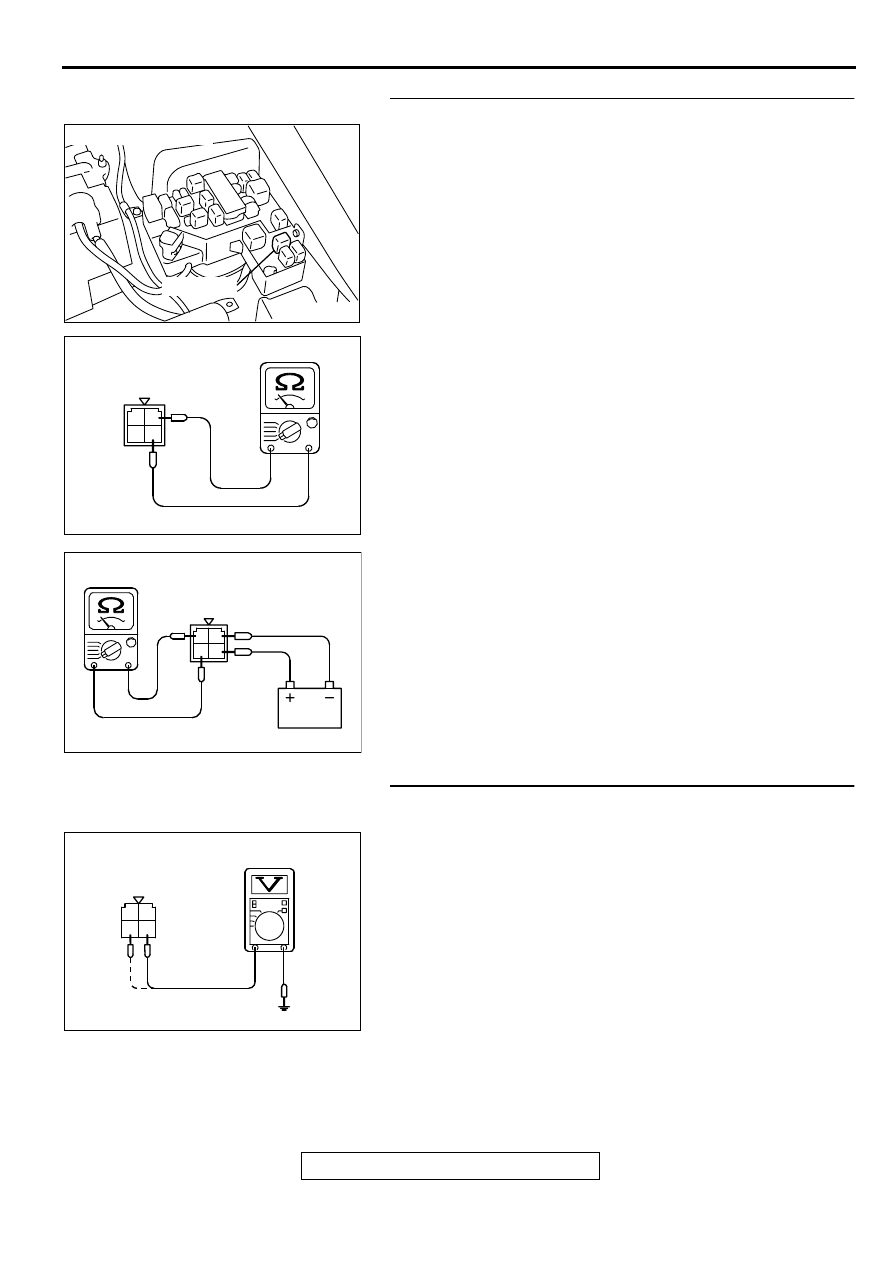
STEP 2. Check the MFI relay
(1) Remove the MFI relay.
(2) Check for continuity between the MFI relay terminals 2 and
4.
•
There should be continuity (approximately 70
Ω
)
(3) Use jumper wires to connect MFI relay terminal 4 to the
positive battery terminal and terminal 2 to the negative
battery terminal.
(4) Check the continuity between the MFI relay terminals 1 and
3 while connecting and disconnecting the jumper wire at
the negative battery terminal.
•
Should be less than 2 ohm.(Negative battery terminal
connected)
•
Should be open loop.(Negative battery terminal
disconnected)
(5) Install the MFI relay.
Q: Is the voltage normal?
YES : Go to Step 3.
NO : Replace the MFI relay. Then confirm that the
malfunction symptom is eliminated.
STEP 3. Check the power supply voltage at MFI relay
harness side connector A-21X.
(1) Disconnect the connector A-21X and measure at the
harness side.
(2) Measure the voltage between terminal 3, 4 and ground.
•
Voltage should be battery positive voltage.
Q: Is the voltage normal?
YES : Go to Step 4.
NO : Check harness connector C-07 at intermediate
connector for damage, and repair or replace as
required. Refer to, GROUP 00E, Harness Connector
Inspection (
). If intermediate connector is in
good condition, repair harness wire between fusible
link (13) and MFI relay connector A-21X terminal 3, 4
because of open circuit. Then confirm that the
malfunction symptom is eliminated.
AK000226
AK000226AB
CONNECTOR : A-21X
MFI RELAY
AK000369AB
MFI RELAY SIDE
CONNECTOR
1 2
3 4
AK000370AB
MFI RELAY SIDE
CONNECTOR
1 2
3 4
AK000371AB
1
2
3
4
A-21X HARNESS
SIDE CONNECTOR
Нет комментариевНе стесняйтесь поделиться с нами вашим ценным мнением.
Текст