Mitsubishi Eclipse / Eclipse Spyder (2000-2002). Service and repair manual — part 461
AUTOMATIC TRANSAXLE DIAGNOSIS
TSB Revision
AUTOMATIC TRANSAXLE
23A-136
CIRCUIT OPERATION
•
Battery positive voltage is applied to the Park/
Neutral position switch (terminal 8) when the
ignition switch is turned "ON."
•
Battery positive voltage is applied to the PCM
(terminal 101) when the selector lever is in the
"P" range. The PCM judges that the selector
lever is in the "P" range when the battery positive
voltage is applied.
•
Battery positive voltage is applied to the PCM
[terminals 108, 121, 102, 109, 122 or 110] when
the selector lever is in the "R" range ("N," "D," "3,"
"2" or "L" range). The PCM judges that the
selector lever is in the "R" range ("N," "D," "3," "2"
or "L" range) when the battery positive voltage is
applied.
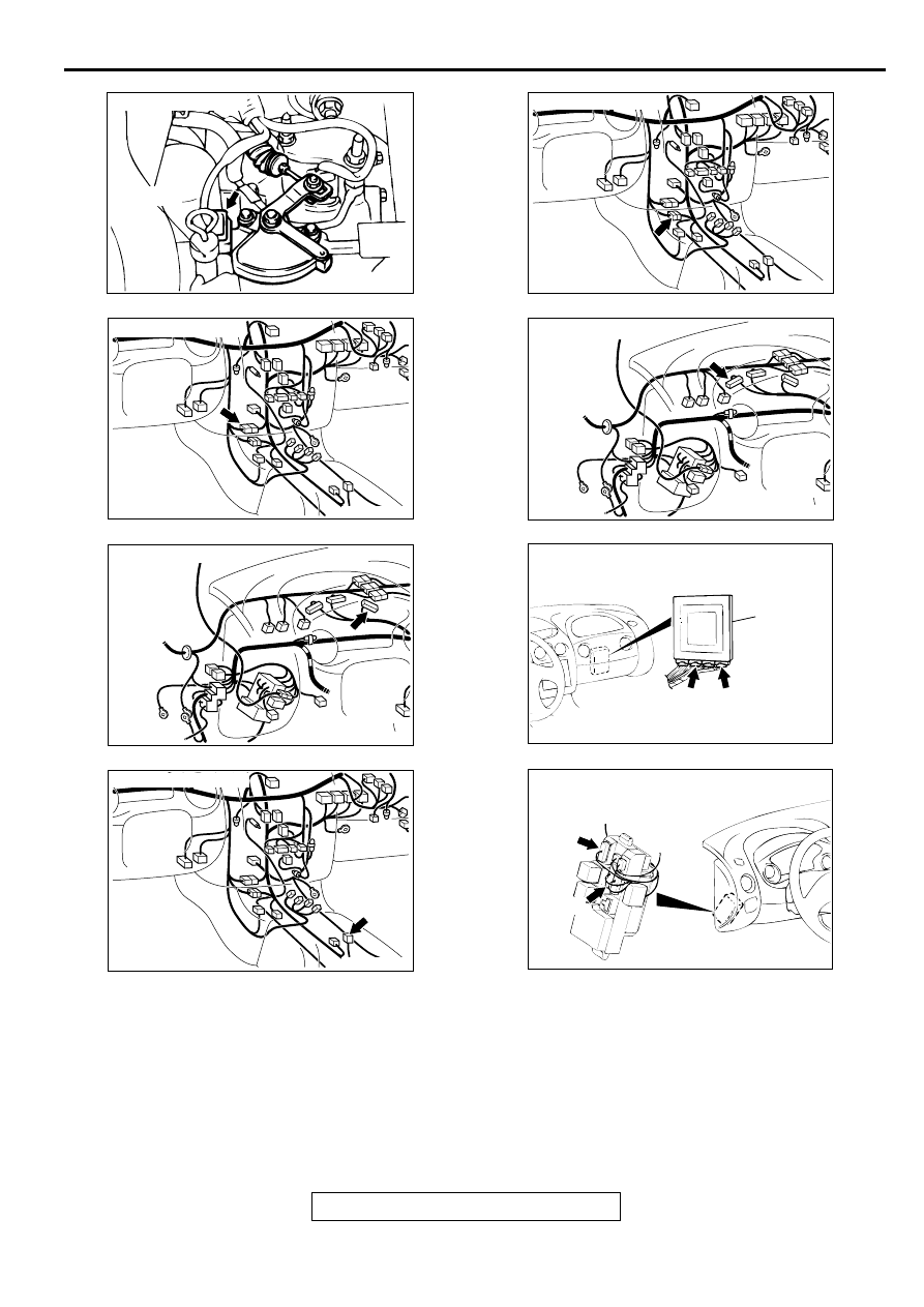
AC001844
CONNECTOR: B-41
DIPSTICK
AB
AC001741
CONNECTOR: C-27
AK
AC001741 AJ
CONNECTOR: C-28
AC001729 AN
CONNECTOR: C-41
AC001729 AO
CONNECTOR: C-43
AC001657
CONNECTORS: C-54 <2.4L ENGINE> OR
C-55 <3.0L ENGINE>, C-61 <2.4L ENGINE>
OR C-63 <3.0L ENGINE>
PCM
AM
C-54 <2.4L ENGINE>
OR
C-55 <3.0L ENGINE>
C-61 <2.4L ENGINE>
OR
C-63 <3.0L ENGINE>
AC001741
CONNECTOR: C-65
AL
AC001691
CONNECTORS: C-101, C-107
C-101
JUNCTION BLOCK
(FRONT VIEW)
C-107
AN
AUTOMATIC TRANSAXLE DIAGNOSIS
TSB Revision
AUTOMATIC TRANSAXLE
23A-137
DTC SET CONDITIONS
If the PCM detects no Park/Neutral position switch
input signal from any selector position for continuous
period of thirty seconds, it is judged that there is an
open circuit in the Park/Neutral position switch and
diagnostic trouble code number "27" is output.
TROUBLESHOOTING HINTS (The most likely
causes for this code to be set:)
•
Malfunction of the Park/Neutral position switch
•
Malfunction of the ignition switch
•
Damaged harness, connector
•
Malfunction of the PCM
DIAGNOSIS
Required Special Tool:
MB991502: Scan Tool (MUT-II)
STEP 1. Using scan tool MB991502, check data list item 61:
Park/Neutral Position Switch.
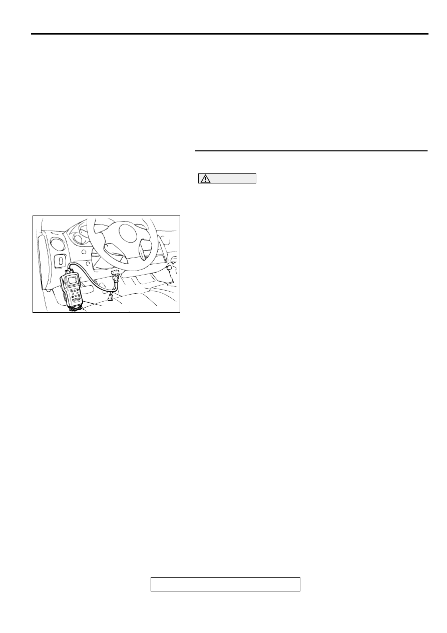
CAUTION
To prevent damage to scan tool MB991502, always turn the
ignition switch to "LOCK" (OFF) position before
connecting or disconnecting scan tool MB991502.
(1) Connect scan tool MB991502 to the data link connector.
(2) Turn the ignition switch to "ON" position.
(3) Set scan tool MB991502 to data reading mode for item 61:
Park/Neutral Position Switch.
•
Move the selector lever to "P," "R," "N," "D," "3," "2," "L"
and sport mode positions to confirm whether the MUT-II.
(The sport mode is indicated as "D" on the MUT-II.)
(4) Turn the ignition switch to "LOCK" (OFF) position.
Q: Is the switch operating properly?
YES : This malfunction can be intermittent. Refer to GROUP
00, How to Use Troubleshooting/Inspection Service
Points
−
How to Cope with Intermittent Malfunction
NO : When indication disagrees at all positions: Go to Step
2. When indication disagrees at "P" position: Go to
Step 6. When indication disagrees at "R" position: Go
to Step 13. When indication disagrees at "N" position:
Go to Step 20. When indication disagrees at "D"
position: Go to Step 26. When indication disagrees at
"3" position: Go to Step 33. When indication
disagrees at "2" position: Go to Step 37. When
indication disagrees at "L" position: Go to Step 41.
When indication disagrees at sport mode position
(agrees at "D" position): Go to Step 45.
AC001252
MB991502
16 PIN
AB
AUTOMATIC TRANSAXLE DIAGNOSIS
TSB Revision
AUTOMATIC TRANSAXLE
23A-138
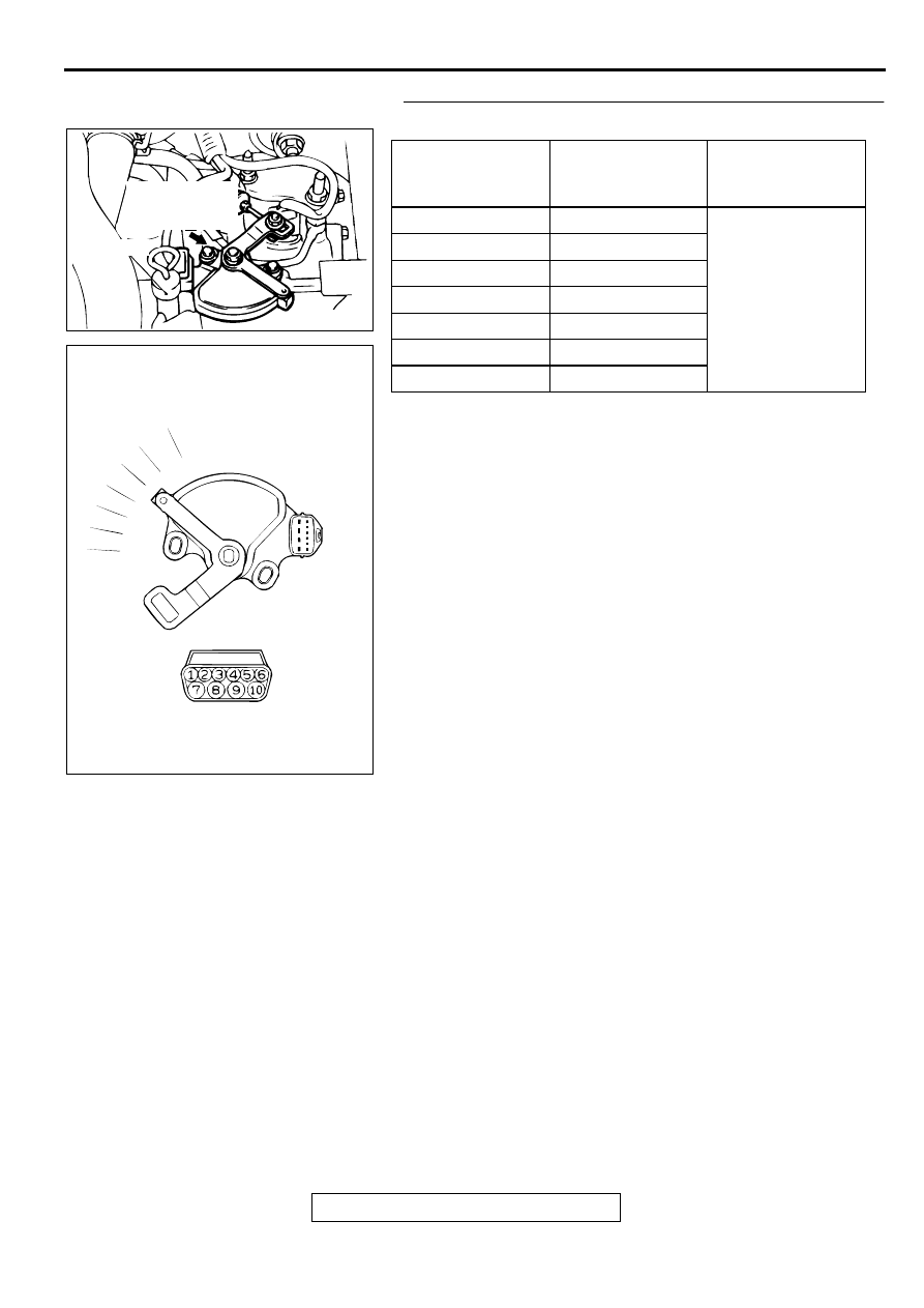
STEP 2. Check the Park/Neutral position switch.
Check for continuity between terminals for each selector
position.
NOTE: For vehicles with sport mode, four positions (P, R, N, D)
are used.
Q: Is the switch operating properly?
YES : Go to Step 3.
NO : Replace the Park/Neutral position switch. Refer to
GROUP 23B, Transaxle
.
ITEMS
TERMINAL
CONNECTION OF
TESTER
SPECIFIED
CONDITION
P
3 - 8, 9 - 10
Less than 2 ohm.
R
7 - 8
N
4 - 8, 9 - 10
D
1 - 8
3
5 - 8
2
2 - 8
L
6 - 8
AC004672
DIPSTICK
PARK/NEUTRAL
POSITION (PNP)
SWITCH
AC
AC001846
P
R
N
D
3
2
L
AB
AUTOMATIC TRANSAXLE DIAGNOSIS
TSB Revision
AUTOMATIC TRANSAXLE
23A-139
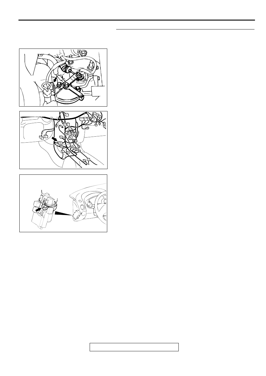
STEP 3. Check connectors B-41 at Park/Neutral position
switch, C-28 at intermediate connector and C-107 at
junction block for damage.
Q: Are the connectors in good condition?
YES : Go to Step 4.
NO : Repair or replace it. Refer to GROUP 00E, Harness
Connector Inspection
.
AC001844
CONNECTOR: B-41
DIPSTICK
AB
AC001741 AJ
CONNECTOR: C-28
AC001691
CONNECTOR: C-107
JUNCTION BLOCK
(FRONT VIEW)
AO
Нет комментариевНе стесняйтесь поделиться с нами вашим ценным мнением.
Текст