Mitsubishi Eclipse / Eclipse Spyder (2000-2002). Service and repair manual — part 353
INTAKE MANIFOLD <3.0L>
TSB Revision
INTAKE AND EXHAUST
15-13
REMOVAL SERVICE POINT
<<A>> FUEL RAIL, INJECTOR AND FUEL PRESSURE
REGULATOR REMOVAL
CAUTION
Care must be taken when removing the fuel rail not to drop
the injector.
Remove the fuel rail with the injectors and pressure regulator
attached to it.
INSTALLATION SERVICE POINTS
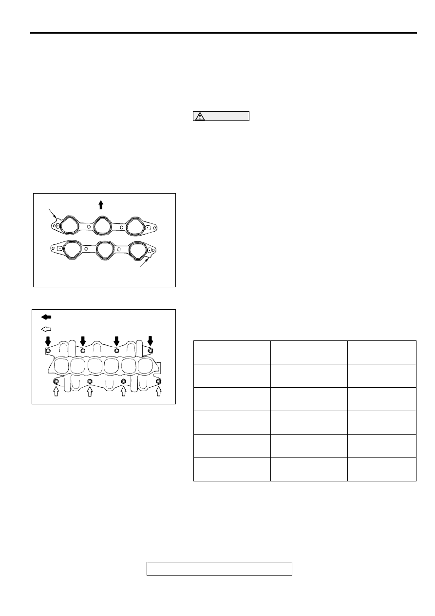
>>A<< INTAKE MANIFOLD GASKET INSTALLATION
Install the gasket with the protrusions in the position illustrated.
>>B<< INTAKE MANIFOLD INSTALLATION
1. Coat the intake manifold mounting studs with engine oil.
2. Tighten the intake manifold mounting nuts by the following
procedure.
>>B<<
12. INTAKE MANIFOLD
>>A<<
13. INTAKE MANIFOLD GASKET
REMOVAL STEPS (Continued)
ACX02434 AC
PROTRUSION
PROTRUSION
FRONT OF VEHICLE
ORDER
MOUNTING NUTS
TIGHTENING
TORQUE
1st
Right-bank nuts
6.4
±
1.4 N
⋅
m
(56
±
13 in-lb)
2nd
Left-bank nuts
22
±
1 N
⋅
m
(16
±
1 ft-lb)
3rd
Right-bank nuts
22
±
1 N
⋅
m
(16
±
1 ft-lb)
4th
Left-bank nuts
22
±
1 N
⋅
m
(16
±
1 ft-lb)
5th
Right-bank nuts
22
±
1 N
⋅
m
(16
±
1 ft-lb)
AC001433
RIGHT BANK
LEFT BANK
AB
INTAKE MANIFOLD <3.0L>
TSB Revision
INTAKE AND EXHAUST
15-14
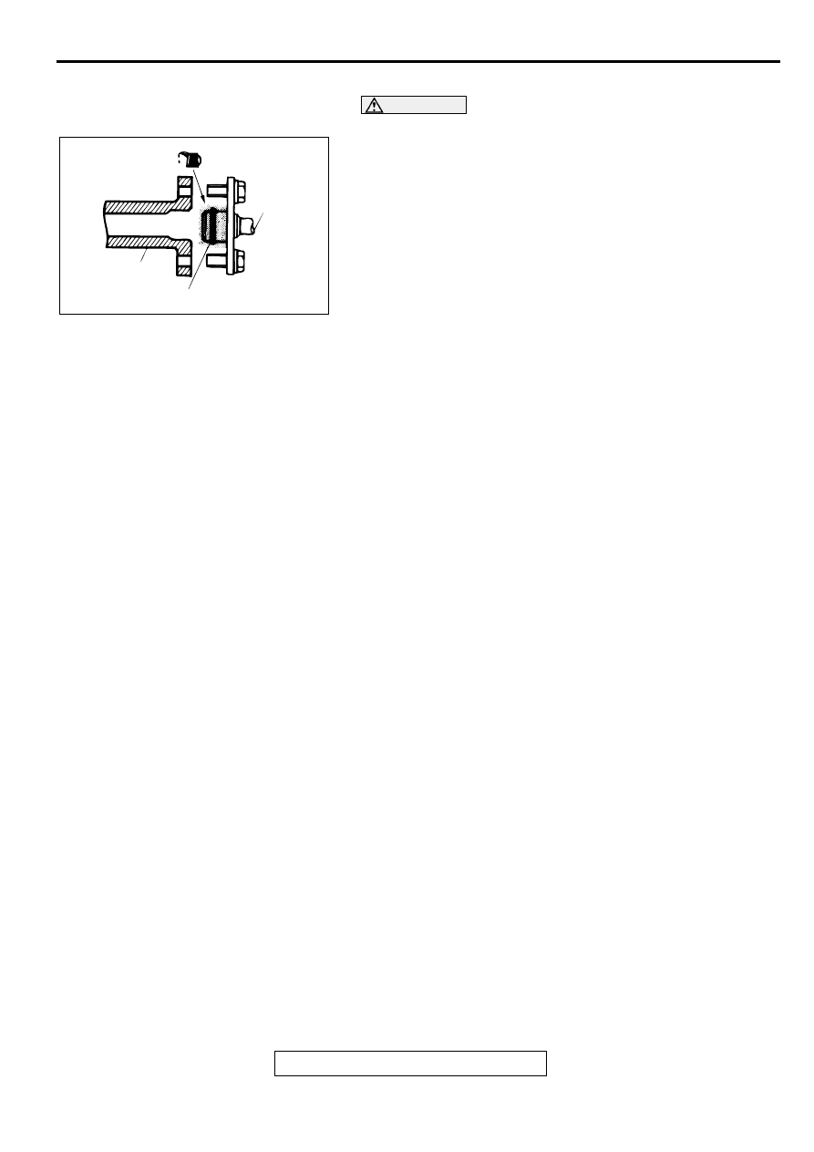
>>C<< HIGH-PRESSURE FUEL HOSE INSTALLATION
CAUTION
Be careful not to allow any engine oil to enter the fuel rail.
1. When connecting the high-pressure fuel hose to the fuel rail,
apply a small amount of new engine oil to the O-ring and
then insert the high-pressure fuel hose, being careful not to
damage the O-ring.
2. While turning the high-pressure fuel hose to the left and
right, install it to the fuel rail.
3. Check that the injector turns smoothly. If it does not turn
smoothly, the O-ring may be trapped. Remove the high-
pressure fuel hose and then re-insert it into the fuel rail and
check again.
INSPECTION
M1151003100122
Check the following points; replace the part if a problem is
found.
INTAKE MANIFOLD CHECK
1. Check for damage or cracking of any part.
2. Check for obstruction of the negative pressure (vacuum)
outlet port, and for obstruction of the water passage or gas
passage.
3. Using a straight edge and feeler gauge, check for distortion
of the cylinder head installation surface.
Standard value: 0.15 mm (0.006 inch) or less
Limit: 0.20 mm (0.008 inch)
AC001436
HIGH-
PRESSURE
FUEL HOSE
FUEL RAIL
O-RING
AB
EXHAUST MANIFOLD <2.4L>
TSB Revision
INTAKE AND EXHAUST
15-15
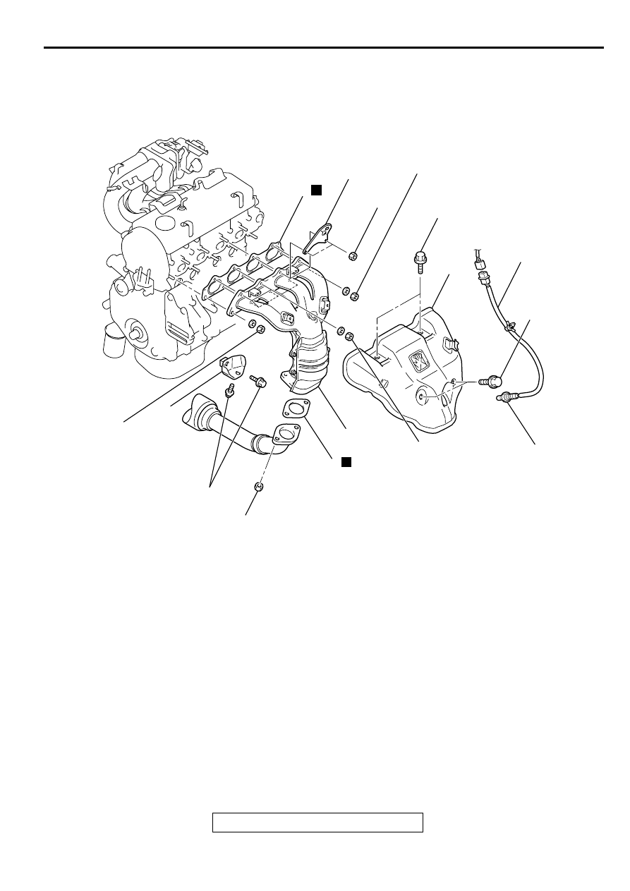
EXH AU ST M AN IFO LD <2.4L>
REMOVAL AND INSTALLATION
M1151003300115
AC001808
44 ± 5 N·m
33 ± 3 ft-lb
29 ± 3 N·m
22 ± 2 ft-lb
49 ± 5 N·m
36 ± 4 ft-lb
49 ± 5 N·m
36 ± 4 ft-lb
29 ± 3 N·m
22 ± 2 ft-lb
14 ± 1 N·m
120 ± 13 in-lb
14 ± 1 N·m
120 ± 13 in-lb
35 ± 6 N·m
26 ± 4 ft-lb
1
49 ± 10 N·m
37 ± 7 ft-lb
2
3
4
5
6
N
N
AD
7
REMOVAL STEPS
<<A>> >>A<<
1. HEATED OXYGEN SENSOR
(FRONT)
2. HEAT PROTECTOR
3. ENGINE HANGER
4. EXHAUST MANIFOLD
5. EXHAUST MANIFOLD GASKET
6. GASKET
7. EXHAUST MANIFOLD BRACKET
REMOVAL STEPS (Continued)
EXHAUST MANIFOLD <2.4L>
TSB Revision
INTAKE AND EXHAUST
15-16
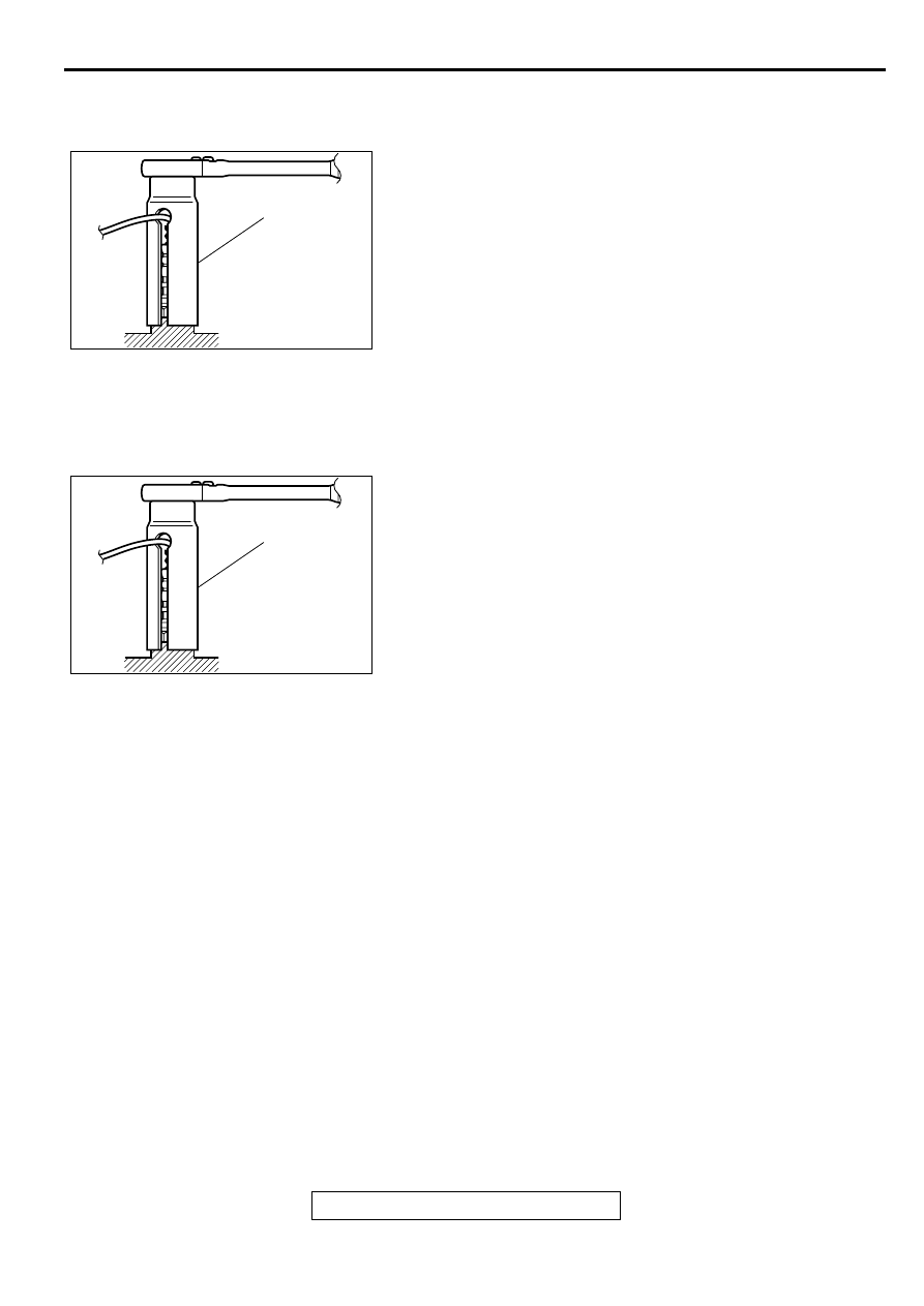
REMOVAL SERVICE POINT
<<A>> HEATED OXYGEN SENSOR (FRONT) REMOVAL
Use special tool MD998770 to remove the oxygen sensor.
INSTALLATION SERVICE POINT
>>A<< HEATED OXYGEN SENSOR (FRONT)
INSTALLATION
Use special tool MD998770 to installation the oxygen sensor.
INSPECTION
M1151003400101
Check the following points; replace the part if a problem is
found.
EXHAUST MANIFOLD CHECK
1. Check for damage or cracking of any part.
2. Using a straight edge and a feeler gauge, check for
distortion of the cylinder head installation surface.
Standard value: 0.15 mm (0.006 inch) or less
Limit: 0.20 mm (0.008 inch)
ACX02426 AB
MD998770
ACX02426 AB
MD998770
Нет комментариевНе стесняйтесь поделиться с нами вашим ценным мнением.
Текст