Mitsubishi Eclipse / Eclipse Spyder (2000-2002). Service and repair manual — part 164
MULTIPORT FUEL INJECTION (MFI) DIAGNOSIS
TSB Revision
MULTIPORT FUEL INJECTION (MFI) <2.4L ENGINE>
13A-355
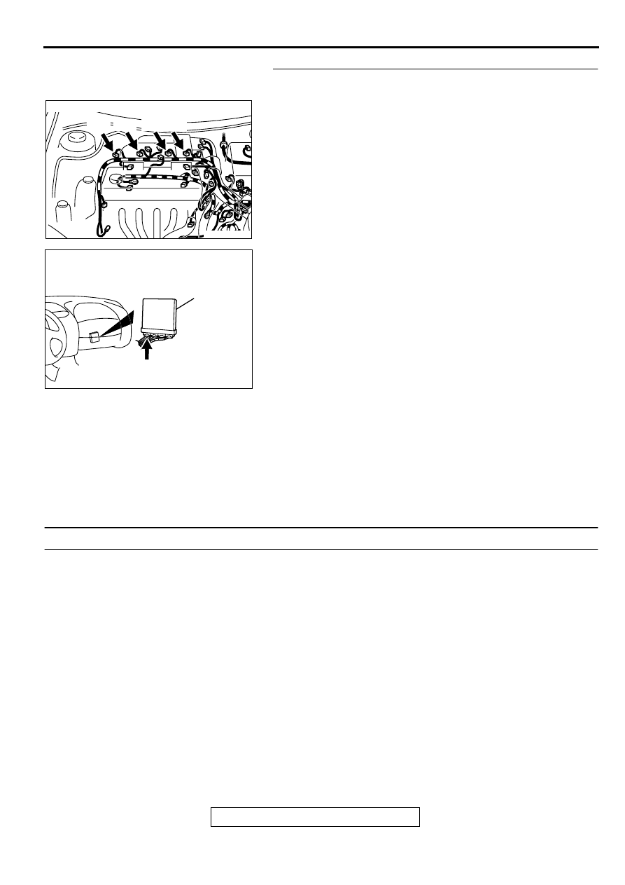
STEP 10. Check for harness damage between injector
connector and ECM <M/T> or PCM <A/T> connector.
a. Check the harness wire between injector connector B-01
terminal 2 and ECM connector C-49 terminal 1 <M/T> or
PCM connector C-50 terminal 1<A/T> when checking No.1
cylinder.
b. Check the harness wire between injector connector B-02
terminal 2 and ECM connector C-49 terminal 14 <M/T> or
PCM connector C-50 terminal 9<A/T> when checking No.2
cylinder.
c. Check the harness wire between injector connector B-05
terminal 2 and ECM connector C-49 terminal 2 <M/T> or
PCM connector C-50 terminal 24<A/T> when checking
No.3 cylinder.
d. Check the harness wire between injector connector B-06
terminal 2 and ECM connector C-49 terminal 15 <M/T> or
PCM connector C-50 terminal 2<A/T> when checking No.4
cylinder.
Q: Is the harness wire in good condition?
YES : Check the following items, and repair or replace the
defective items.
a. Check the ignition coil, spark plugs, spark plug
cables.
b. Check if the injectors are clogged.
c. Check if fuel is contaminated.
d. Check compression.
Then confirm that the malfunction symptom is
eliminated.
NO : Repair it. Then confirm that the malfunction symptom
is eliminated.
INSPECTION PROCEDURE 6: Fires Up and Dies.
COMMENT
•
In such cases as the above, the cause is usually
improper air/fuel mixture. It is possible, though
less likely, that the spark plugs are generating
sparks but the sparks are weak.
TROUBLESHOOTING HINTS (The most likely
causes for this case:)
•
Malfunction of the ignition system.
•
Malfunction of the injector system.
•
Contaminated fuel.
•
Poor compression.
•
Malfunction of the ECM <M/T> or PCM <A/T>.
DIAGNOSIS
Required Special Tool:
MB991502: Scan Tool (MUT-II)
AK000273AB
AK000273
CONNECTOR : B-01, B-02, B-05, B-06
B-01 B-02 B-05 B-06
AK000280
C-49,C-50
ECM<M/T>
OR
PCM<A/T>
CONNECTORS:C-49<M/T>,C-50<A/T>
BC
MULTIPORT FUEL INJECTION (MFI) DIAGNOSIS
TSB Revision
MULTIPORT FUEL INJECTION (MFI) <2.4L ENGINE>
13A-356
STEP 1. Check the battery positive voltage.
(1) Measure the battery positive voltage during cranking.
•
The voltage should be 8 volts or more.
Q: Is the voltage normal?
YES : Go to Step 2.
NO : Refer to GROUP 8A, Battery-Battery check (
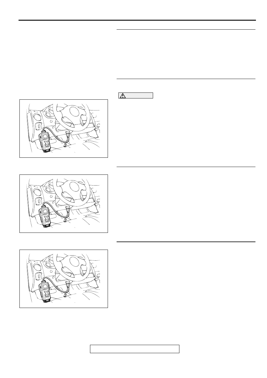
STEP 2. Using scan tool MB991502, read the diagnostic
trouble code (DTC).
CAUTION
To prevent damage to scan tool MB991502, always turn the
ignition switch to the "LOCK" (OFF) position before
connecting or disconnecting scan tool MB991502.
(1) Connect scan tool MB991502 to the data link connector.
(2) Turn the ignition switch to the "ON" position.
(3) Read the DTC.
(4) Turn the ignition switch to the "LOCK" (OFF) position.
Q: Is the DTC is output?
YES : Refer to, Diagnostic Trouble Code Chart (
NO : Go to Step 3.
STEP 3. Using scan tool MB991502, check actuator test.
(1) Turn the ignition switch to the "ON" position.
(2) Check the following items in the actuator test. Refer to,
Actuator Test Reference Table (
).
a. Item 07: Fuel Pump.
(3) Turn the ignition switch to the "LOCK" (OFF) position.
Q: Is the actuator operating properly?
YES : Go to Step 4.
NO : Repair or replace. Then confirm that the malfunction
symptom is eliminated.
STEP 4. Using scan tool MB991502, check data list.
(1) Turn the ignition switch to the "ON" position.
(2) Check the following items in the data list. Refer to, Data List
Reference Table (
a. Item 21: Engine Coolant Temperature Sensor.
(3) Turn the ignition switch to the "LOCK" (OFF) position.
Q: Is the sensor operating properly?
YES : Go to Step 5.
NO : Repair or replace. Then confirm that the malfunction
symptom is eliminated.
AKX01177
16 PIN
MB991502
AB
AKX01177
16 PIN
MB991502
AB
AKX01177
16 PIN
MB991502
AB
MULTIPORT FUEL INJECTION (MFI) DIAGNOSIS
TSB Revision
MULTIPORT FUEL INJECTION (MFI) <2.4L ENGINE>
13A-357
STEP 5. Check the engine start-ability.
(1) Depress the accelerator pedal slightly, and start the engine.
Q: Is the start ability good?
YES : Go to Step 6.
NO : Go to Step 7.
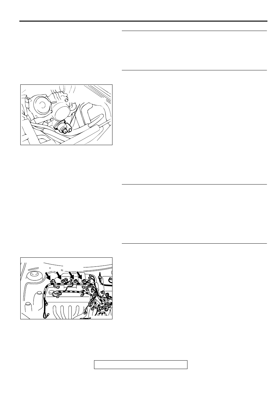
STEP 6. Check the idle air control (IAC) motor operation
sound.
(1) Check that the engine coolant temperature is 20
°
C (68
°
F)
or below.
NOTE: If necessary, you can disconnect the engine coolant
temperature sensor connector and connect the harness
side of the connector to another engine coolant temperature
sensor that is at 20
°
C(68
°
F) or below.
(2) Check that the operation sound of the IAC motor can be
heard after the ignition is switched to the "ON" position (but
without starting the engine).
•
An operation sound is heard.
Q: Did you hear the operation sound?
YES : Refer to, Clean the throttle valve area (
NO : Refer to DTC P0506 Idle Control System RPM Lower
Than Expected (
), DTC P0507 Idle Control
System RPM Higher Than Expected (
STEP 7. Check the ignition timing.
(1) Check the ignition timing at cranking.
Standard value: 5
°
BTDC
±
3
°
Q: Is the ignition timing normal?
YES : Go to Step 8.
NO : Check that the crankshaft position sensor and timing
belt cover are in the correct position. Then confirm
that the malfunction symptom is eliminated.
STEP 8. Check harness connector B-01 or B-02 or B-05 or
B-06 at injector for damage.
Q: Is the harness connector in good condition?
YES : Go to Step 9.
NO : Repair or replace it. Refer to GROUP 00E, Harness
Connector Inspection (
). Then confirm that
the malfunction symptom is eliminated.
ACX02519 AI
IDLE AIR
CONTROL MOTOR
CONNECTOR:B-34
AK000273AB
AK000273
CONNECTOR : B-01, B-02, B-05, B-06
B-01 B-02 B-05 B-06
MULTIPORT FUEL INJECTION (MFI) DIAGNOSIS
TSB Revision
MULTIPORT FUEL INJECTION (MFI) <2.4L ENGINE>
13A-358
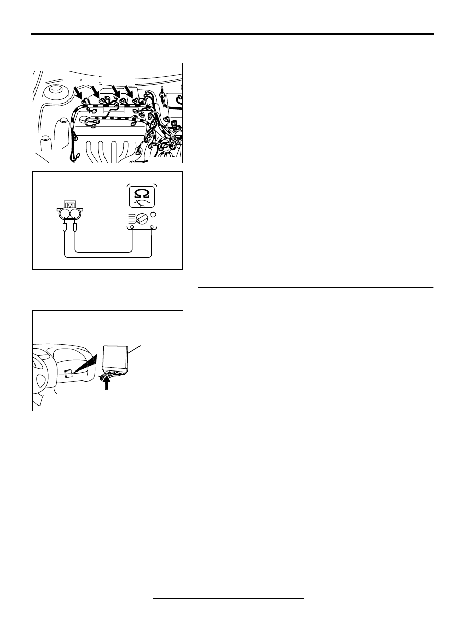
STEP 9. Check the injector.
(1) Disconnect the injector connector B-01, B-02, B-05, B-06.
(2) Measure the resistance between each injector side
connector terminal 1 and 2.
Standard value:13-16 ohm [at 20
°
C (68
°
F)]
Q: Is the resistance standard value?
YES : Go to Step 10.
NO : Repair the injector. Then confirm that the malfunction
symptom is eliminated.
STEP 10. Check connector C-49 at ECM <M/T> or
connector C-50 at PCM <A/T> for damage.
Q: Is the connector in good condition?
YES : Go to Step 11.
NO : Repair or replace it. Refer to GROUP 00E, Harness
Connector Inspection (
). Then confirm that
the malfunction symptom is eliminated.
AK000273AB
AK000273
CONNECTOR : B-01, B-02, B-05, B-06
B-01 B-02 B-05 B-06
AK000559
2
1
INJECTOR SIDE
CONNECTOR
AB
AK000280
C-49,C-50
ECM<M/T>
OR
PCM<A/T>
CONNECTORS:C-49<M/T>,C-50<A/T>
BC
Нет комментариевНе стесняйтесь поделиться с нами вашим ценным мнением.
Текст