Mitsubishi Eclipse / Eclipse Spyder (2000-2002). Service and repair manual — part 597
TRACTION CONTROL SYSTEM (TCL) DIAGNOSIS
TSB Revision
TRACTION CONTROL SYSTEM (TCL)
35C-23
INSPECTION PROCEDURE 3: When the Ignition Key is Turned to "ON" (Engine Stopped), the TCL
Warning Light does not Illuminate.
NOTE: CONNECTOR LOCK SWITCH
ON: The ABS-ECU connector A-02 is connected.
OFF: The ABS-ECU connector A-02 is disconnected.
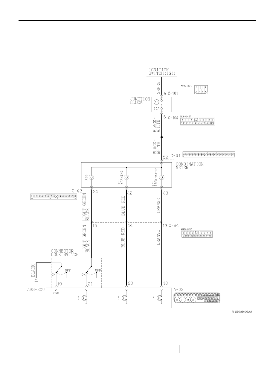
TCL Warning Light and TCL Indicator Light Circuit
TRACTION CONTROL SYSTEM (TCL) DIAGNOSIS
TSB Revision
TRACTION CONTROL SYSTEM (TCL)
35C-24
CIRCUIT OPERATION
•
Power to the TCL warning light is supplied from
the ignition switch. The ABS-ECU grounds the
circuit to illuminate the light.
•
The ABS-ECU illuminates the TCL warning light
for three seconds on start-up <ignition key: "ON"
(with engine stopped)>. When the ABS-ECU
completes the self-check, it turns off the light.
TECHNICAL DESCRIPTION (COMMENT)
The cause may be: an open circuit in the TCL
warning light power supply circuit, a blown TCL
warning light bulb or ABS-ECU malfunction.
TROUBLESHOOTING HINTS (The most likely
causes for this case:)
•
Blown fuse
•
Damaged wiring harness or connector
•
Burnt out TCL warning light bulb
•
Malfunction of the ABS-ECU
DIAGNOSIS
Required Special Tool:
•
MB991223: Harness Set
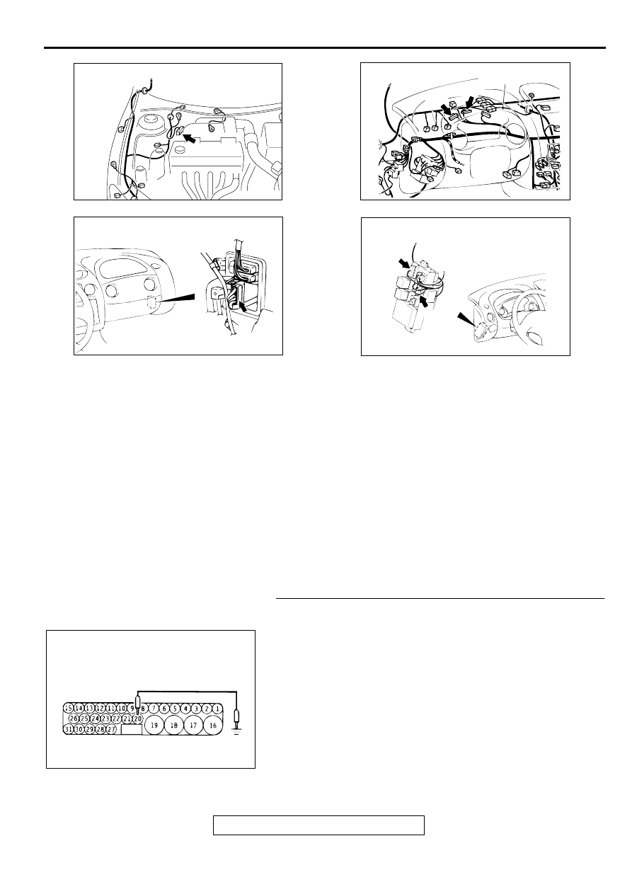
STEP 1. Check the TCL warning light circuit at the ABS-
ECU connector A-02.
(1) Disconnect the ABS-ECU connector A-02 and measure at
the harness side.
(2) Ground the terminal 20.
(3) Turn the ignition switch to the "ON" position.
Q: Does the TCL warning light illuminate?
YES : Replace the hydraulic unit (integrated with ABS-ECU)
(Refer to GROUP 35B, Hydraulic Unit
.) and
then go to Step 9.
NO : Go to Step 2.
AC001985
CONNECTOR: A-02
AD
AC004428 AB
CONNECTORS: C-41, C-42
C-41
C-42
COMBINATION
METER
AC003604 AB
CONNECTOR: C-94
CONNECTOR
BLOCK (RH)
AC004411AB
CONNECTORS: C-101, C-104
C-104
C-101
AC000970
A-02 (HARNESS SIDE)
AB
TRACTION CONTROL SYSTEM (TCL) DIAGNOSIS
TSB Revision
TRACTION CONTROL SYSTEM (TCL)
35C-25
STEP 2. Check the TCL warning light bulb.
(1) Remove the combination meter (Refer to GROUP 54A,
Combination Meter
and
.).
(2) Check the TCL warning light bulb.
Q: Is the TCL warning light bulb burned out?
YES : Replace the bulb and then go to Step 9.
NO : Go to Step 3.
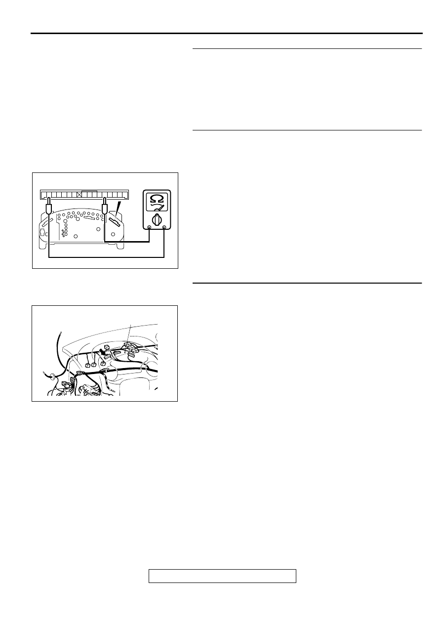
STEP 3. Check the combination meter for the continuity.
(1) Remove the combination meter.
(2) Remove the TCL warning light bulb. Then measure the
resistance between the bulb terminals.
(3) Install the TCL warning light bulb to the combination meter,
and then measure the resistance between the connector C-
41 terminals 52 and 42. The resistance reading at this time
should be much the same as the resistance measured at
step (2).
Q: Are the two resistance values extremely different each
other?
YES : Replace the combination meter (printed circuit board)
and then go to Step 9.
NO (much the same) : Go to Step 4.
STEP 4. Check the power supply circuit at the combination
meter.
(1) Disconnect the combination meter connector C-41, and
check at the harness side.
(2) Turn the ignition switch to the "ON" position.
(3) Measure the voltage between the terminal 52 and ground. It
should be approximately 12 volts (battery positive voltage.).
Q: Is the voltage approximately 12 volts (battery positive
voltage)?
YES : Go to Step 5.
NO : Go to Step 7.
41 42 43 44 45 46 47
48 49 50 51 52 53 54 55 56
AC004565 AB
CONNECTOR C-41
AC004482 AB
CONNECTOR: C-41
COMBINATION METER
TRACTION CONTROL SYSTEM (TCL) DIAGNOSIS
TSB Revision
TRACTION CONTROL SYSTEM (TCL)
35C-26
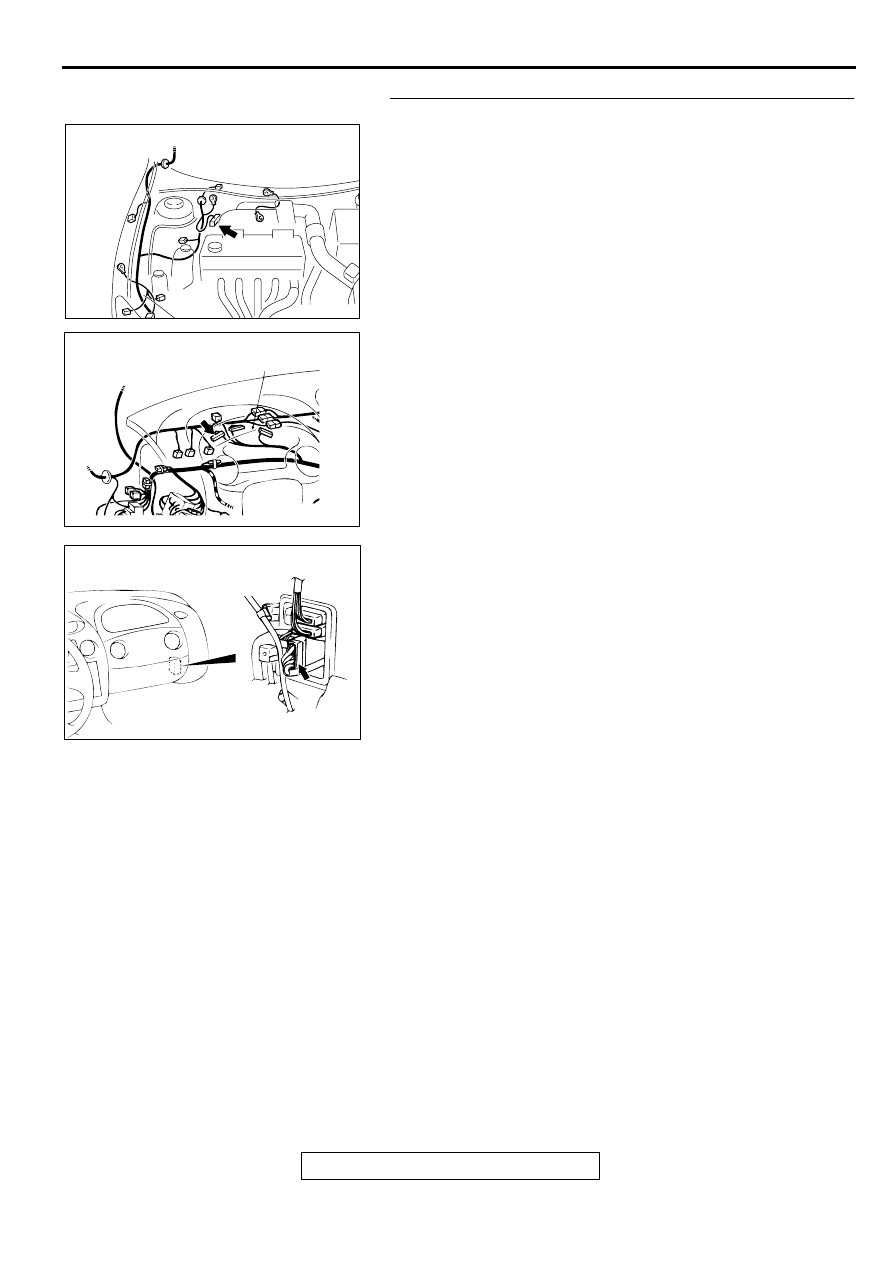
STEP 5. Check the connectors A-02, C-41, and C-94.
Refer to GROUP 00E, Harness Connector Inspection
Q: Is any of the connectors damaged?
YES : Repair it and then go to Step 9.
NO : Go to Step 6.
AC001985
CONNECTOR: A-02
AD
AC004482 AB
CONNECTOR: C-41
COMBINATION METER
AC003604 AB
CONNECTOR: C-94
CONNECTOR
BLOCK (RH)
Нет комментариевНе стесняйтесь поделиться с нами вашим ценным мнением.
Текст