Mitsubishi Eclipse / Eclipse Spyder (2000-2002). Service and repair manual — part 482
AUTOMATIC TRANSAXLE DIAGNOSIS
TSB Revision
AUTOMATIC TRANSAXLE
23A-220
DTC 41: 1st Gear Incorrect Ratio
DTC 42: 2nd Gear Incorrect Ratio
DTC 43: 3rd Gear Incorrect Ratio
DTC 44: 4th Gear Incorrect Ratio
DTC 46: Reverse Gear Incorrect Ratio
AC004691
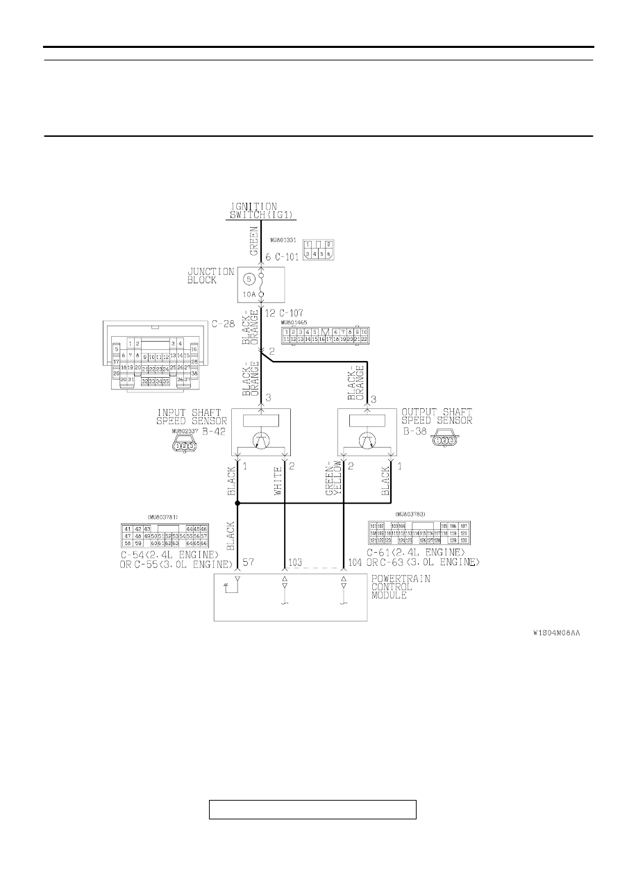
Input Shaft Speed Sensor and Output Shaft Speed Sensor System Circuit
AC
AUTOMATIC TRANSAXLE DIAGNOSIS
TSB Revision
AUTOMATIC TRANSAXLE
23A-221
CIRCUIT OPERATION
•
A coil built into the input shaft speed sensor
generates pulse signal of 0
⇔
5 volts at both
ends of this coil when the input shaft rotates. The
pulse signal frequency increases with the rise in
input shaft speed.
•
Both ends of the coil are connected to the PCM
(terminals 57 and 103) via the input shaft speed
sensor connector (terminals 1 and 2).
•
The PCM detects the input shaft speed with the
signal input to terminal (terminal 103).
•
A coil built into the output shaft speed sensor
generates pulse signal of 0
⇔
5 volts at both
ends of this coil when the output shaft rotates.
The pulse signal frequency increases with the
rise in output shaft speed.
•
Both ends of the coil are connected to the PCM
(terminals 57 and 104) via the output shaft speed
sensor connector (terminals 1 and 2).
•
The PCM detects the output shaft speed with the
signal input to terminal (terminal 104).
DTC SET CONDITIONS
If the output from the output shaft speed sensor
multiplied by the 1st gear ratio is not the same as the
output from the input shaft speed sensor after
shifting to 1st gear has been completed, diagnostic
trouble code number "41" is output. If diagnostic
trouble code number "41" is output four times, the
transmission is locked into 3rd gear as a fail-safe
measure, and the "N" range light flashes once per
second.
TROUBLESHOOTING HINTS (The most likely
causes for this code to be set:)
•
Malfunction of the input shaft speed sensor
•
Malfunction of the output shaft speed sensor
•
Malfunction of the PCM
•
Malfunction of the underdrive clutch retainer
•
Malfunction of the transfer drive gear or driven
gear
•
Malfunction of the low-reverse brake system (for
code number "41," "46")
•
Malfunction of the underdrive clutch system (for
code number "41," "42," "43")
•
Malfunction of the second brake system (for code
number "42," "44")
•
Malfunction of the overdrive clutch system (for
code number "43," "44")
•
Malfunction of the reverse clutch system (for
code number "46")
•
Noise generated
AC001850 AD
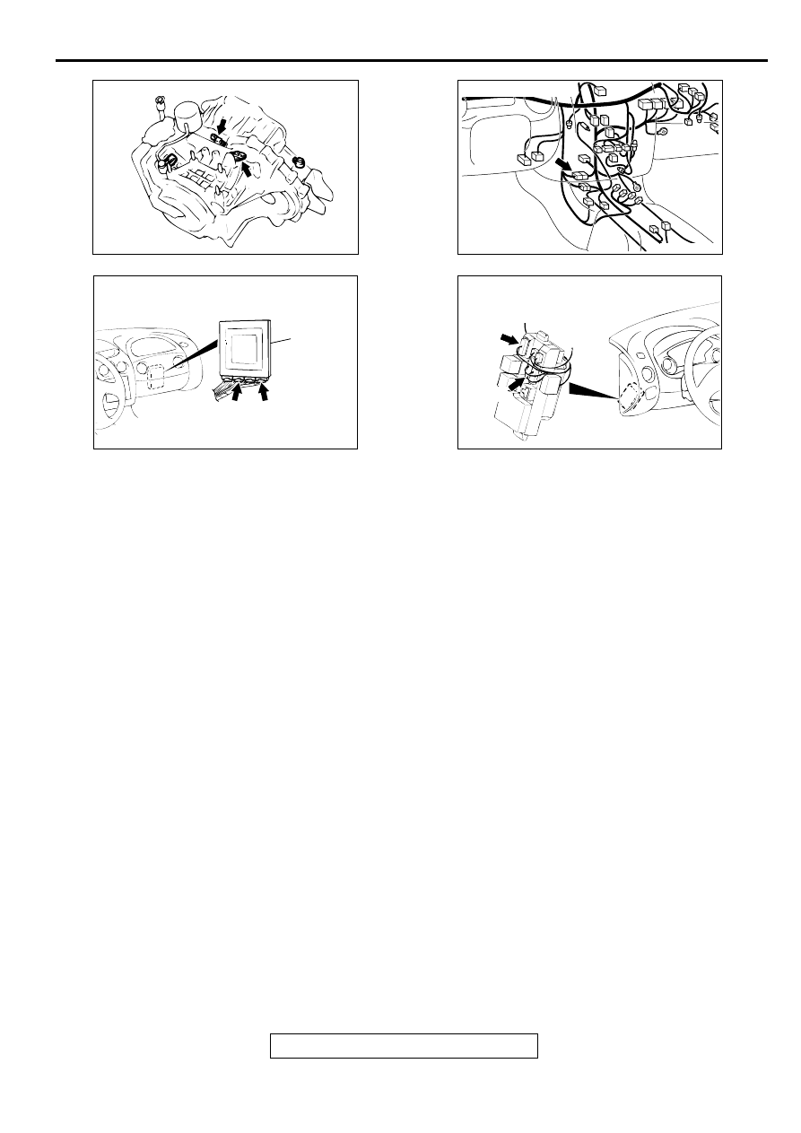
CONNECTORS: B-38, B-42
B-38
B-42
AC001741 AJ
CONNECTOR: C-28
AC001657
CONNECTORS: C-54 <2.4L ENGINE> OR
C-55 <3.0L ENGINE>, C-61 <2.4L ENGINE>
OR C-63 <3.0L ENGINE>
PCM
AM
C-54 <2.4L ENGINE>
OR
C-55 <3.0L ENGINE>
C-61 <2.4L ENGINE>
OR
C-63 <3.0L ENGINE>
AC001691
CONNECTORS: C-101, C-107
C-101
JUNCTION BLOCK
(FRONT VIEW)
C-107
AN
AUTOMATIC TRANSAXLE DIAGNOSIS
TSB Revision
AUTOMATIC TRANSAXLE
23A-222
DIAGNOSIS
Required Special Tool:
MB991502: Scan Tool (MUT-II)
STEP 1. Using scan tool MB991502, read the A/T
diagnostic trouble code.
CAUTION
To prevent damage to scan tool MB991502, always turn the
ignition switch to "LOCK" (OFF) position before
connecting or disconnecting scan tool MB991502.
(1) Connect scan tool MB991502 to the data link connector.
(2) Turn the ignition switch to the "ON" position.
(3) Read the A/T diagnostic trouble code.
(4) Turn the ignition switch to "LOCK" (OFF) position.
Q: Is A/T diagnostic trouble code numbers "22" or "23"
, code number 22: Input Shaft
Speed Sensor System, or refer to
, code
number 23: Output Shaft Speed Sensor System.
NO : Go to Step 2.
STEP 2. Using scan tool MB991502, check actuator test.
(1) Connect scan tool MB991502 to the data link connector.
(2) Turn the ignition switch to "ON" position.
(3) Set scan tool MB991502 to actuator test mode for following
items.
a. item 01: Low-reverse Solenoid Valve
b. item 02: Underdrive Solenoid Valve
c. item 03: Second Solenoid Valve
d. item 04: Overdrive Solenoid Valve
•
An operation sound should be heard from solenoid
valve when solenoid valve is operated.
(4) Turn the ignition switch to "LOCK" (OFF) position.
Q: Is the solenoid valve operating properly?
YES : Go to Step 3.
NO : Replace the corresponding solenoid valve. Refer to
GROUP 23B, Valve Body
.
AC001252
MB991502
16 PIN
AB
AC001252
MB991502
16 PIN
AB
AUTOMATIC TRANSAXLE DIAGNOSIS
TSB Revision
AUTOMATIC TRANSAXLE
23A-223
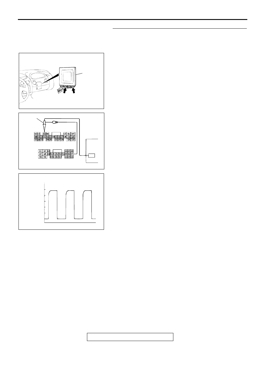
STEP 3. Using the oscilloscope, check the waveform at
PCM connectors C-54 <2.4L Engine> or C-55 <3.0L
Engine> and C-61 <2.4L Engine> or C-63 <3.0L Engine> by
backprobing.
(1) Do not disconnect connectors C-54 <2.4L Engine> or C-55
<3.0L Engine> and C-61 <2.4L engine> or C-63 <3.0L
Engine>.
(2) Connect an oscilloscope probe to PCM connector C-54
<2.4L Engine> or C-55 <3.0L Engine> terminal 57 and to
PCM connector C-61 <2.4L engine> or C-63 <3.0L Engine>
terminal 103 by backprobing.
(3) Start the engine and run at constant speed of 50km/h
(31mph). (Gear range: 3rd gear)
(4) Check the waveform.
•
The waveform should show a pattern similar to the
illustration. The maximum value should be 4.8 volts and
more and the minimum value 0.8 volts and less. The
output waveform should not contain the noise.
(5) Turn the ignition switch to "LOCK" (OFF) position.
Q: Is the waveform normal?
YES : Go to Step 8.
NO : Go to Step 4.
AC001657
CONNECTORS: C-54 <2.4L ENGINE> OR
C-55 <3.0L ENGINE>, C-61 <2.4L ENGINE>
OR C-63 <3.0L ENGINE>
PCM
AM
C-54 <2.4L ENGINE>
OR
C-55 <3.0L ENGINE>
C-61 <2.4L ENGINE>
OR
C-63 <3.0L ENGINE>
AC001899
C-61 <2.4L ENGINE> OR C-63 <3.0L ENGINE>
CONNECTOR HARNESS SIDE VIEW
C-54 <2.4L ENGINE> OR C-55 <3.0L ENGINE>
CONNECTOR HARNESS SIDE VIEW
AD
OSCILLO-
SCOPE
PROBE
ACX02131AB
NORMAL WAVEFORM
(V)
5
0
Нет комментариевНе стесняйтесь поделиться с нами вашим ценным мнением.
Текст