Mitsubishi Eclipse / Eclipse Spyder (2000-2002). Service and repair manual — part 80

MULTIPORT FUEL INJECTION (MFI) DIAGNOSIS
TSB Revision
MULTIPORT FUEL INJECTION (MFI) <2.4L ENGINE>
13A-19
READINESS TEST STATUS
PURPOSE
The Readiness function also referred as I/M
Readiness or I/M Flags indicate if a full diagnostic
check has been "Completed" (is "Ready") for each
non-continuous monitor. Enhanced I/M State
Emission Programs will use the Readiness status
(Codes) to see if the vehicle is ready for OBD-II
testing. "Incomplete" (Not Ready) codes will be one
of the triggers for I/M failure.
OVERVIEW
The engine control module (ECM) <M/T> or
powertrain control module (PCM) <A/T> monitors the
following main diagnosis items and records whether
the evaluation was completed or is incomplete. The
Readiness codes were established for the I/M
programs, thereby confirming that the vehicle was
not tampered with by erasing the diagnostic trouble
code(s) (DTC's) before I/M testing. The Readiness
and DTC codes can be reset by disconnecting the
battery or by erasing the codes with a scan tool. For
this reason all Readiness codes must read
"Complete" before I/M testing.
When the monitors run and complete, the MUT-II will
record the Readiness Code as "Complete" (General
Scan Tools record as "Ready"). If the monitor did not
run completely, the system then reads as
"Incomplete" (General Scan Tools record as "Not
Ready"). When the vehicle is operating normally and
the OBD-II Drive Cycle is carried out, Readiness
Code will set as "Complete" on the first drive cycle. If
during the first drive cycle a fault is detected then, a
second drive is required before the Readiness Code
will "Complete." If the fault is still there, then a DTC
will set.
•
Catalyst: P0421
•
Evaporative system: P0442, P0455
•
Heated oxygen sensor: P0130,P0133,
P0136,P0139
•
Heated oxygen sensor heater: P0135, P0141
•
EGR system: P0401
After the Readiness is "Complete," the technician is
assured that any DTC's associated with that monitor
will be displayed if the system has a problem. That is
why some State's I/M programs require the
Readiness Code as "Complete" before they check
for DTC's.
NOTE: After a repair is mode for a DTC the
technician should drive the OBD-II drive cycle
checking that the MUT-II records all Readiness as
"Complete".
FAIL-SAFE/BACKUP FUNCTION TABLE
M1131009100065
When the main sensor malfunctions are detected by the diagnostic test mode, the vehicle is controlled by
means of the following defaults.
MALFUNCTION ITEM
CONTROL CONTENTS DURING MALFUNCTION
Volume air flow sensor
1. Uses the throttle position sensor signal and engine speed signal (crankshaft
position sensor signal) for basic injector drive time and basic ignition timing
from the pre-set mapping.
2. Fixes the IAC motor in the appointed position so idle air control is not
performed.
Intake air temperature
sensor
Controls as if the intake air temperature is 25
°
C (77
°
F).
Throttle position sensor
No increase in fuel injection amount during acceleration due to the unreliable
throttle position sensor signal.
Engine coolant
temperature sensor
Controls as if the engine coolant temperature is 80
°
C (176
°
F). (This control will
be continued until the ignition switch is turned to the "LOCK" (OFF) position
even though the sensor signal returns to normal.)
Camshaft position sensor Injects fuel simultaneously into all cylinders. (After the ignition switch is turned to
the "ON" position, the No.1 cylinder top dead center is not detected at all.)
Barometric pressure
sensor
Controls as if the barometric pressure is 101 kPa (30 in Hg).
Knock sensor
Switches the ignition timing from ignition timing for high octane to ignition timing
for standard octane fuel.

MULTIPORT FUEL INJECTION (MFI) DIAGNOSIS
TSB Revision
MULTIPORT FUEL INJECTION (MFI) <2.4L ENGINE>
13A-20
DIAGNOSTIC TROUBLE CODE CHART
M1131008700150
Communication line with
transaxle control CPU
No ignition timing retard control (overall engine-transaxle control) achieved
when transaxle speeds are changed.
Generator FR terminal
Does not restrict the generator output with respect to electrical load.
Heated oxygen sensor
<front>
Air/fuel ratio closed loop control is not performed.
Heated oxygen sensor
<rear>
Performs the closed loop control of the air/fuel ratio by using only the signal of
the heated oxygen sensor (front) installed on the front side of the catalytic
converter.
Misfire detection
The ECM <M/T> or PCM <A/T> stops supplying fuel to the cylinder with the
highest misfiring rate if a misfiring that could damage the catalytic converter is
detected.
MALFUNCTION ITEM
CONTROL CONTENTS DURING MALFUNCTION
DTC CODE
DIAGNOSTIC ITEMS
REFERENCE
PAGE
P0101
Volume air flow circuit range/performance problem
P0102
Volume air flow circuit low input
P0103
Volume air flow circuit high input
P0107
Barometric pressure circuit low input
P0108
Barometric pressure circuit high input
P0111
Intake air temperature circuit range/performance problem
P0115
Engine coolant temperature circuit high input
P0116
Engine coolant temperature circuit range/performance problem
P0117
Engine coolant temperature circuit low input
P0121
Throttle position circuit range/performance problem
P0122
Throttle position circuit low input
P0123
Throttle position circuit high input
P0128
Coolant thermostat malfunction
P0130
O
2
Sensor circuit malfunction (sensor 1)
P0133
O
2
Sensor circuit slow response (sensor 1)
P0134O
2
Sensor circuit no activity detected (sensor 1)
P0135
O
2
Sensor heater circuit malfunction (sensor 1)
P0136
O
2
Sensor circuit malfunction (sensor 2)
P0139
O
2
Sensor circuit slow response (sensor 2)
P0141
O
2
Sensor heater circuit malfunction (sensor 2)
P0171
System too lean
P0172
System too rich

MULTIPORT FUEL INJECTION (MFI) DIAGNOSIS
TSB Revision
MULTIPORT FUEL INJECTION (MFI) <2.4L ENGINE>
13A-21
P0201
Injector circuit malfunction
−
Cylinder 1
P0202
Injector circuit malfunction
−
Cylinder 2
P0203
Injector circuit malfunction
−
Cylinder 3
P0204Injector circuit malfunction
−
Cylinder 4
P0300
Random misfire detected
P0301
Cylinder 1 misfire detected
P0302
Cylinder 2 misfire detected
P0303
Cylinder 3 misfire detected
P0304Cylinder 4
misfire detected
P0325
Knock sensor 1 circuit malfunction
P0335
Crankshaft position sensor circuit malfunction
P0340
Camshaft position sensor circuit malfunction
P0401
Exhaust gas recirculation flow insufficient detected
P0403
Exhaust gas recirculation solenoid malfunction
P0421
Warm up catalyst efficiency below threshold
P0442
Evaporative emission control system leak detected
P0443
Evaporative emission control system purge control valve circuit
malfunction
P0446
Evaporative emission control system vent control malfunction
P0450
Evaporative emission control system pressure sensor malfunction
P0451
Evaporative emission control system pressure sensor range/performance
P0455
Evaporative emission control system leak detected (Gross leak)
P0500
Vehicle speed sensor malfunction
<M/T>
, <A/T>
P0506
Idle control system rpm lower than expected
P0507
Idle control system rpm higher than expected
P0551
Power steering pressure sensor circuit range/performance
P0705
Transmission range
sensor circuit
malfunction (PRNDL
input)
•
A/T DTC No.27 (Park/Neutral position
switch system: Open circuit)
•
A/T DTC No.28 (Park/Neutral position
switch system: Short circuit)
P0710
Transmission fluid
temperature sensor
circuit malfunction
•
A/T DTC No.15 (Oil temperature sensor
system: Open circuit)
•
A/T DTC No.16 (Oil temperature sensor
system: Short circuit)
P0715
Input/turbine speed
sensor circuit
malfunction
•
A/T DTC No.22 (Input shaft speed sensor
system)
P0720
Output speed sensor
circuit malfunction
•
A/T DTC No.23 (Output shaft speed sensor
system)
DTC CODE
DIAGNOSTIC ITEMS
REFERENCE
PAGE
MULTIPORT FUEL INJECTION (MFI) DIAGNOSIS
TSB Revision
MULTIPORT FUEL INJECTION (MFI) <2.4L ENGINE>
13A-22
NOTE: Do not replace the engine control module (ECM) <M/T> or powertrain control module (PCM) <A/T>
until a through terminal check reveals there are no short/open circuits.
NOTE: Check that the ECM <M/T> or PCM <A/T> ground circuit is normal before checking for the cause of
the problem.
NOTE: After the ECM <M/T> or PCM <A/T> detects a malfunction, a diagnostic trouble code is recorded the
next time the engine is started and the same malfunction is re-detected. However, for items marked with a "*,"
the diagnostic trouble code is recorded on the first detection of the malfunction.
NOTE: Sensor 1 indicates the sensor mounted at a position closest to the engine, and sensor 2 indicates the
sensor mounted at the position second closest to the engine.
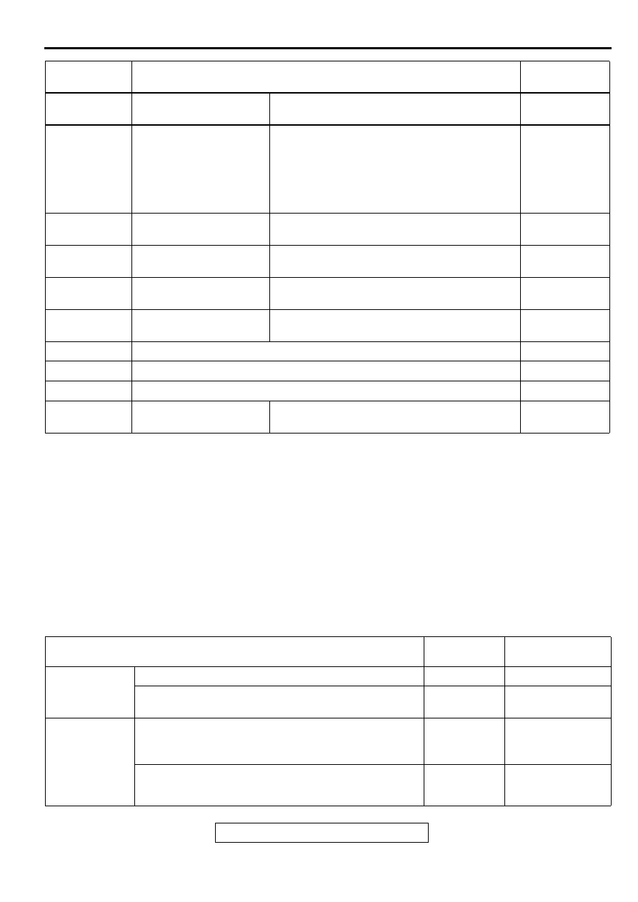
SYMPTOM CHART
M1131008800157
NOTE: Check that the engine control module (ECM) <M/T> or powertrain control module (PCM) <A/T>
ground circuit is normal before checking for the cause of the problem.
P0725
Engine speed input
circuit malfunction
•
A/T DTC No.21 (Crankshaft position sensor
system)
P0740
Torque converter clutch
system malfunction
•
A/T DTC No.36 (Torque converter clutch
solenoid system: Short circuit/Open circuit)
•
A/T DTC No.52 (Torque converter clutch
solenoid system: Faulty system)
•
A/T DTC No.53 (Torque converter clutch
solenoid system: Lock-up stuck on)
P0750
Shift solenoid A
malfunction
•
A/T DTC No.31 (Low and reverse solenoid
valve system)
P0755
Shift solenoid B
malfunction
•
A/T DTC No.32 (Underdrive solenoid valve
system)
P0760
Shift solenoid C
malfunction
•
A/T DTC No.33 (Second solenoid valve
system)
P0765
Shift solenoid D
malfunction
•
A/T DTC No.34 (Overdrive solenoid valve
system)
P1400
Manifold differential pressure sensor circuit malfunction
P1500
Generator FR terminal circuit malfunction
P1610
Immobilizer malfunction
P1751
A/T control relay
malfunction
•
A/T DTC No.54 (A/T control relay system)
DTC CODE
DIAGNOSTIC ITEMS
REFERENCE
PAGE
SYMPTOMS
INSPECTION
PROCEDURE
REFERENCE PAGE
Communication
with scan tool is
impossible
Communication with all systems is not possible
1
Communication with ECM <M/T> or PCM <A/T> only
is not possible
2
Service engine
soon/
malfunction
indicator lamp
and related
parts
The service engine soon/malfunction indicator lamp
does not illuminate right after the ignition switch is
turned to the "ON" position
3
The service engine soon/malfunction indicator lamp
remains illuminated and never goes out
4
Нет комментариевНе стесняйтесь поделиться с нами вашим ценным мнением.
Текст