Mitsubishi Eclipse / Eclipse Spyder (2000-2002). Service and repair manual — part 319
MULTIPORT FUEL INJECTION (MFI) DIAGNOSIS
TSB Revision
MULTIPORT FUEL INJECTION (MFI) <3.0L ENGINE>
13B-475
STEP 11. Using scan tool MB991502, check data list item
69: Right Bank Heated oxygen sensor (rear).
CAUTION
To prevent damage to scan tool MB991502, always turn the
ignition switch to the "LOCK" (OFF) position before
connecting or disconnecting scan tool MB991502.
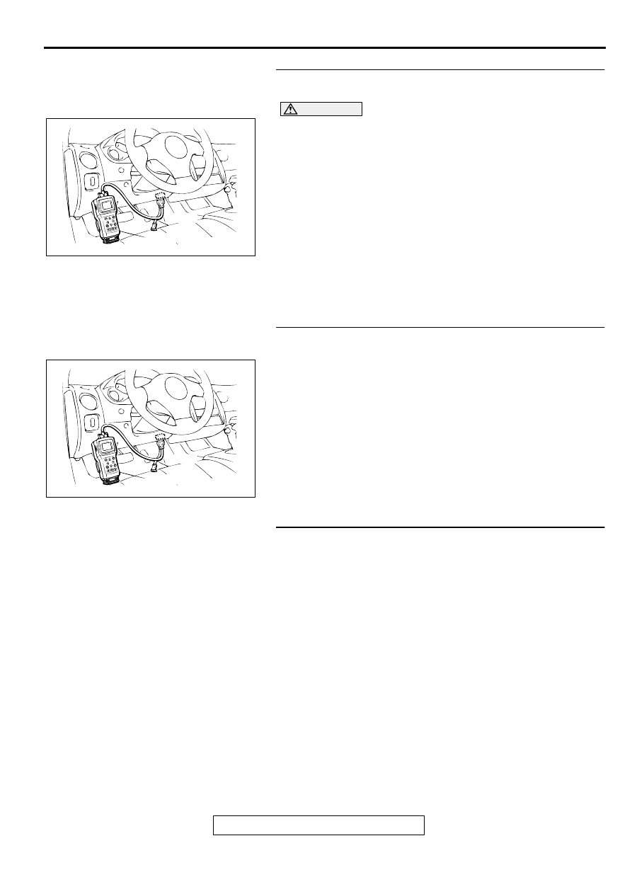
(1) Connect scan tool MB991502 to the data link connector.
(2) Start the engine and run at idle.
(3) Set scan tool MB991502 to the data reading mode for item
69, Right Bank Heated Oxygen Sensor (rear).
•
Average voltage should be 0.6 volts or less, when idling.
(4) Turn the ignition switch to the "LOCK" (OFF) position.
Q: Is the sensor operating properly?
YES : Go to Step 16.
NO : Replace the right bank heated oxygen sensor (front).
Then confirm that the malfunction symptom is
eliminated.
STEP 12. Using scan tool MB991502, check data list item
11: Left Bank Heated oxygen sensor (front).
(1) Start the engine and run at idle.
(2) Set scan tool MB991502 to the data reading mode for item
11, Left Bank Heated Oxygen Sensor (front).
•
Warm up the engine. When the engine is decelerated
suddenly from 4000 r/min, the output voltage should
increase from 200 mV or less to 600
−
1000 mV in a few
seconds.
(3) Turn the ignition switch to the "LOCK" (OFF) position.
Q: Is the sensor operating properly?
YES : Go to Step 13.
NO : Go to Step 15.
STEP 13. Check the EGR system.
Refer to GROUP 17, Emission Control System
−
EGR System
Check (
Q: Is the EGR system normal?
YES : Go to Step 14.
NO : Repair or replace. Then confirm that the malfunction
symptom is eliminated.
AKX01177
16 PIN
MB991502
AB
AKX01177
16 PIN
MB991502
AB
MULTIPORT FUEL INJECTION (MFI) DIAGNOSIS
TSB Revision
MULTIPORT FUEL INJECTION (MFI) <3.0L ENGINE>
13B-476
STEP 14. Using scan tool MB991502, check data list item
59: Left Bank Heated oxygen sensor (rear).
CAUTION
To prevent damage to scan tool MB991502, always turn the
ignition switch to the "LOCK" (OFF) position before
connecting or disconnecting scan tool MB991502.
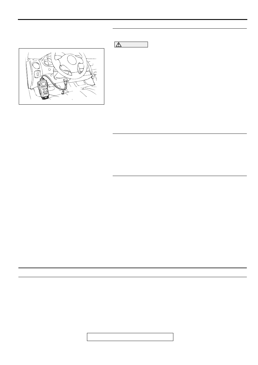
(1) Connect scan tool MB991502 to the data link connector.
(2) Start the engine and run at idle.
(3) Set scan tool MB991502 to the data reading mode for item
59, Left Bank Heated Oxygen Sensor (rear).
•
Average voltage should be 0.6 volts or less, when idling.
(4) Turn the ignition switch to the "LOCK" (OFF) position.
Q: Is the sensor operating properly?
YES : Go to Step 16.
NO : Replace the left bank heated oxygen sensor (front).
Then confirm that the malfunction symptom is
eliminated.
STEP 15. Check the fuel pressure.
Refer to, Fuel Pressure Test (
Q: Is the fuel pressure normal?
YES : Go to Step 16.
NO : Repair or replace. Then confirm that the malfunction
symptom is eliminated.
STEP 16. Check the following items.
(1) Check the following items, and repair or replace the
defective items.
a. Check the injectors for fuel leakage.
b. Check the ignition coil, spark plugs, spark plug cables.
c. Check compression pressure.
d. Check the positive crankcase ventilation system.
e. Check the evaporative emission control system.
(2) Then check the malfunction symptom.
Q: Is the malfunction symptom is eliminated?
YES : The check is completed.
NO : Replace the catalytic converter. Then confirm that the
malfunction symptom is eliminated.
INSPECTION PROCEDURE 24: Purge Flow Test of the Evaporative Emission Canister Failure.
COMMENT
•
The test fails when the purge line or purge port is
clogged or if the evaporative emission purge
solenoid fails.
TROUBLESHOOTING HINTS (The most likely
causes for this case:)
•
Purge line or purge port is clogged.
•
Malfunction of the evaporative emission purge
solenoid.
•
Evaporative emission canister is clogged.
AKX01177
16 PIN
MB991502
AB
MULTIPORT FUEL INJECTION (MFI) DIAGNOSIS
TSB Revision
MULTIPORT FUEL INJECTION (MFI) <3.0L ENGINE>
13B-477
DIAGNOSIS
Required Special Tool:
MB991502: Scan Tool (MUT-II)
STEP 1. Using scan tool MB991502, read the diagnostic
trouble code (DTC).
CAUTION
To prevent damage to scan tool MB991502, always turn the
ignition switch to the "LOCK" (OFF) position before
connecting or disconnecting scan tool MB991502.
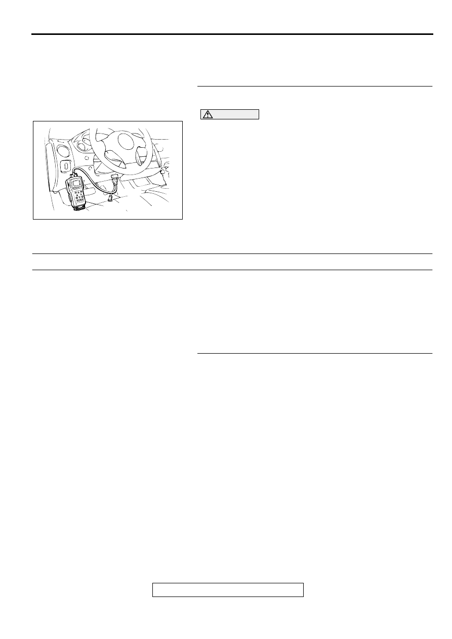
(1) Connect scan tool MB991502 to the data link connector.
(2) Turn the ignition switch to the "ON" position.
(3) Read the DTC.
(4) Turn the ignition switch to the "LOCK" (OFF) position.
Q: Is the DTC is output?
YES : Refer to, Diagnostic Trouble Code Chart (
NO : Refer to GROUP 17, Emission Control System-Purge
Control System Check (Purge Flow Check) (
INSPECTION PROCEDURE 25: Pressure Test of the Evaporative System Failure.
COMMENT
•
The test fails if there is a leak from the fuel tank or
vapor line.
TROUBLESHOOTING HINTS (The most likely
causes for this case:)
•
Loose fuel tank filler tube cap.
•
Broken seal in fuel tank, vapor line evaporative
emission canister.
DIAGNOSIS
STEP 1. Check the evaporative emission purge solenoid
Refer to GROUP 17, Emission Control System
−
Evaporative
Emission Purge Solenoid Check (Check (
).
Q: Is the evaporative emission purge solenoid normal?
YES : Go to Step 2.
NO : Repair or replace. Then confirm that the malfunction
symptom is eliminated.
AKX01177
16 PIN
MB991502
AB
MULTIPORT FUEL INJECTION (MFI) DIAGNOSIS
TSB Revision
MULTIPORT FUEL INJECTION (MFI) <3.0L ENGINE>
13B-478
STEP 2. Check the evaporative emission ventilation
solenoid.
Refer to GROUP 17, Emission Control System
−
Evaporative
Emission Ventilation Solenoid Check (
Q: Is the evaporative emission ventilation solenoid
normal?
YES : Check the following items, and repair or replace the
defective items.
a. Check for leaks from the vapor line or
evaporative emission canister.
b. Check for leaks from the fuel tank.
Then confirm that the malfunction symptom is
eliminated.
NO : Repair or replace. Then confirm that the malfunction
symptom is eliminated.
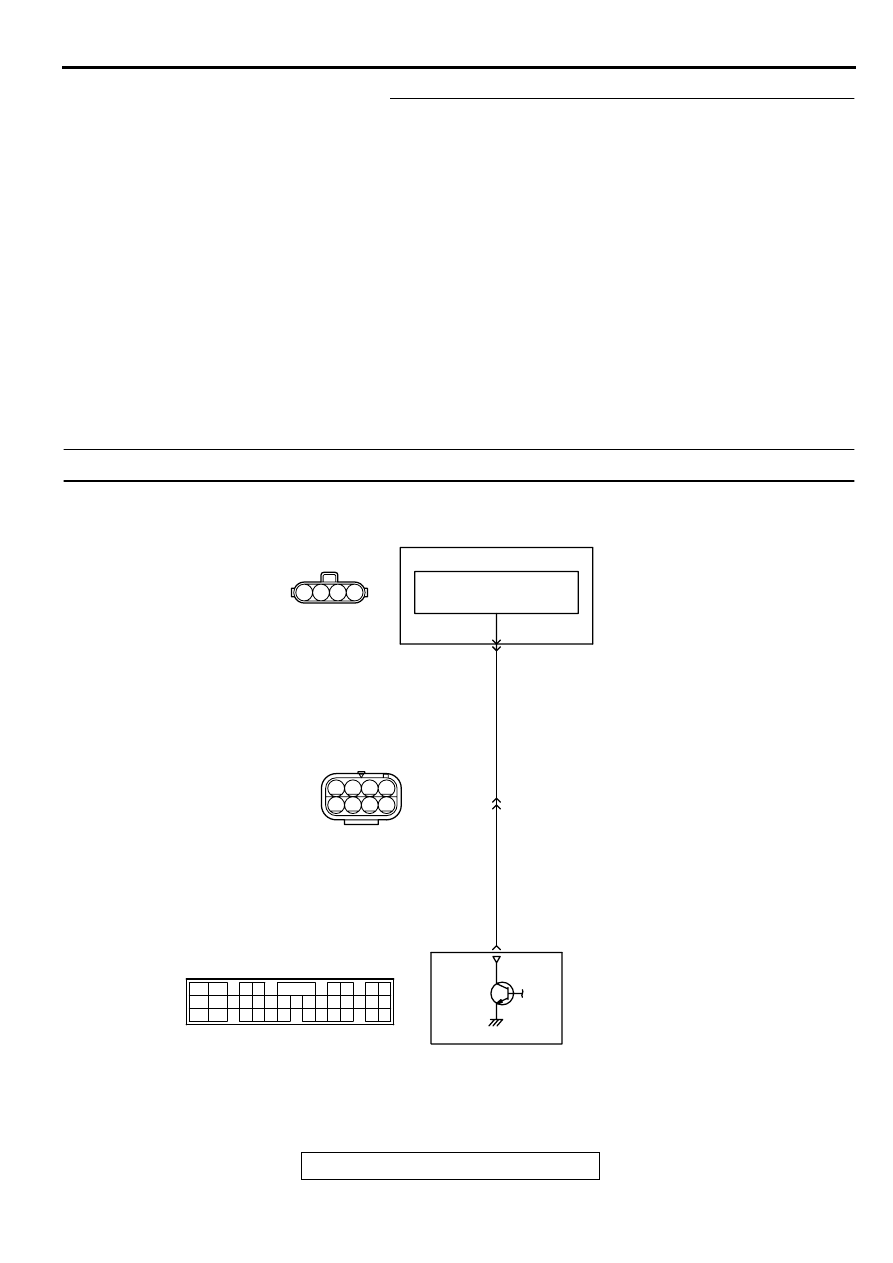
INSPECTION PROCEDURE 26: Generator output voltage is low (approximately 12.3 volts)
AK000713
4
3
2
6
3 4
7 8
1 2
5
1
BL
ACK
-RED
BL
ACK
-RED
ENGINE CONTROL
MODULE(ECM)<M/T>
OR
POWERTRAIN CONTROL
MODULE(PCM)<A/T>
GENERATOR
VOLTAGE
REGULATOR
B-45
1
2
B-13
MU802749
8
C-51<M/T>,C-52<A/T>
(MU803784)
2
3 4
5 6
7 8
9
11 12 13 14 15 16 17 18 19 20
30
21 22 23
24 25
26 27 28 29
3132 33
34 35
1
10
(MU802046)
Нет комментариевНе стесняйтесь поделиться с нами вашим ценным мнением.
Текст