Mitsubishi Eclipse / Eclipse Spyder (2000-2002). Service and repair manual — part 91
MULTIPORT FUEL INJECTION (MFI) DIAGNOSIS
TSB Revision
MULTIPORT FUEL INJECTION (MFI) <2.4L ENGINE>
13A-63
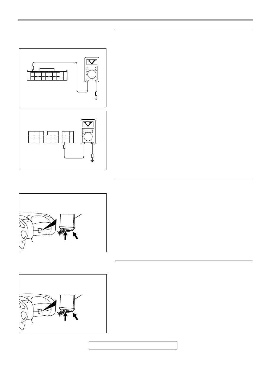
STEP 8. Check the sensor supply voltage at ECM
connector C-60 <M/T> or PCM connector C-54 <A/T> by
backprobing.
(1) Do not disconnect the ECM connector C-60 <M/T> or PCM
connector C-54 <A/T>.
(2) Disconnect the intake air temperature sensor connector B-
14.
(3) Turn the ignition switch to the "ON" position.
(4) Measure the voltage between terminal 72 <M/T> or 64 <A/
T> and ground by backprobing.
•
Voltage should be between 4.5 and 4.9 volts.
(5) Turn the ignition switch to the "LOCK" (OFF) position.
Q: Is the voltage normal?
YES : Go to Step 9.
NO : Go to Step 10.
STEP 9. Check connector C-60 at ECM <M/T> or connector
C-54 at PCM <A/T> for damage.
Q: Is the connector in good condition?
YES : Repair harness wire between intake air temperature
sensor connector B-14 terminal 6 and ECM connector
C-60 terminal 72 <M/T> or PCM connector C-54
terminal 64 <A/T> because of open circuit. Then go to
Step 19.
NO : Repair or replace it. Refer to GROUP 00E, Harness
Connector Inspection (
). Then go to Step 19.
STEP 10. Check connector C-60 at ECM <M/T> or
connector C-54 at PCM <A/T> for damage.
Q: Is the connector in good condition?
YES : Go to Step 11.
NO : Repair or replace it. Refer to GROUP 00E, Harness
Connector Inspection (
). Then go to Step 19.
AK000285
7172 73 74 75 76 77 78 79 80 81
82 83 84 85 86 87 88 89 90
92
91
AC
<M/T>
C-60 CONNECTOR
HARNESS SIDE VIEW
AK000286
C-54 CONNECTOR
HARNESS SIDE VIEW
46
57
66
45
56
65
44
55
43
49
54
64
42
48
59
41
47
58
53
63
52
62
51
61
50
60
AD
<A/T>
AK000280
C-54
C-60
ECM<M/T>
OR
PCM<A/T>
CONNECTORS:C-60<M/T>,C-54<A/T>
BB
AK000280
C-54
C-60
ECM<M/T>
OR
PCM<A/T>
CONNECTORS:C-60<M/T>,C-54<A/T>
BB
MULTIPORT FUEL INJECTION (MFI) DIAGNOSIS
TSB Revision
MULTIPORT FUEL INJECTION (MFI) <2.4L ENGINE>
13A-64
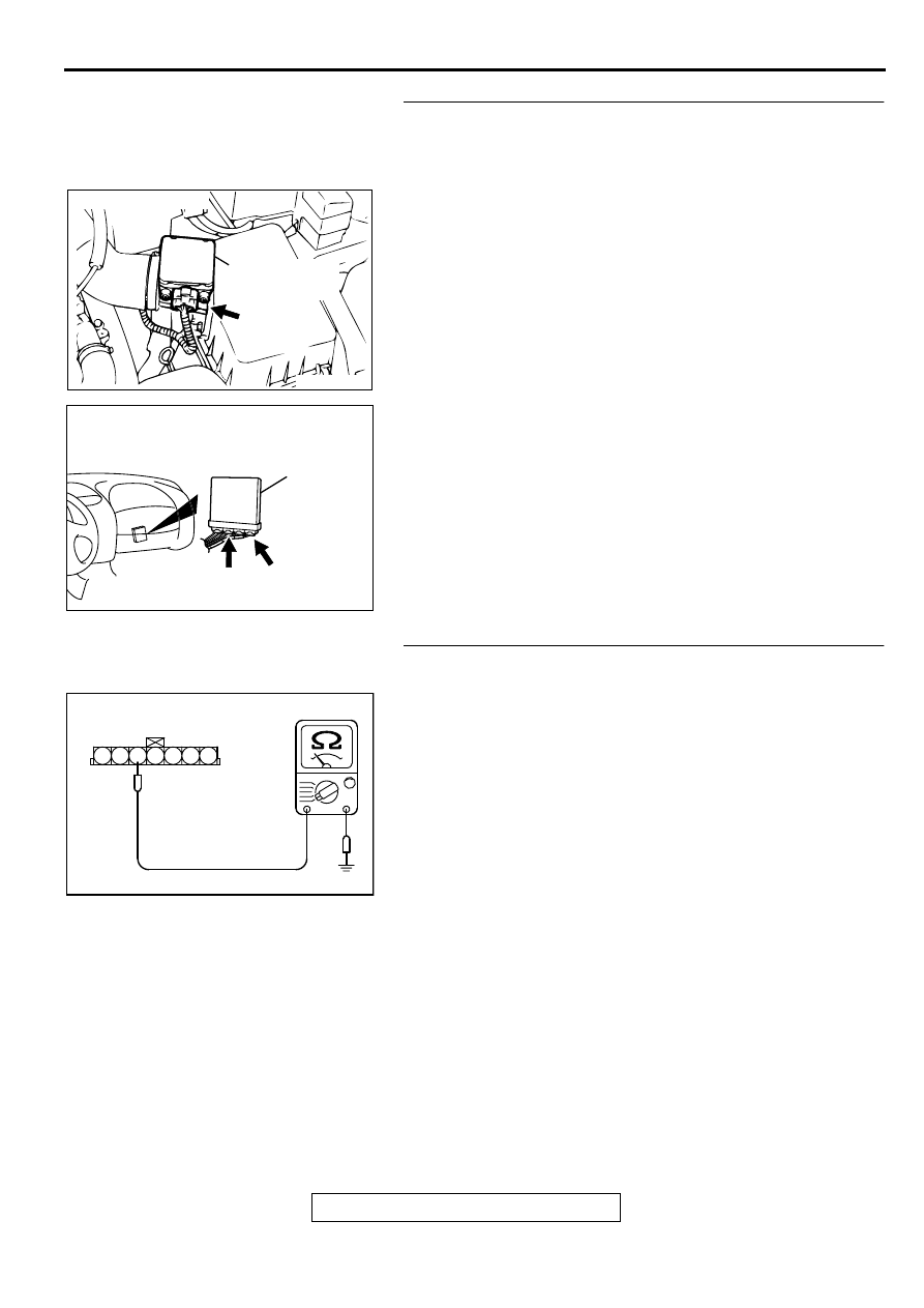
STEP 11. Check for short circuit to ground between intake
air temperature sensor connector B-14 terminal 6 and ECM
connector C-60 terminal 72 <M/T> or PCM connector C-54
terminal 64 <A/T>.
Q: Is the harness wire in good condition?
YES : Replace the ECM or PCM. Then go to Step 19.
NO : Repair it. Then go to Step 19.
STEP 12. Check the continuity at intake air temperature
sensor harness side connector B-14.
(1) Disconnect the connector B-14 and measure at the harness
side.
(2) Check for the continuity between terminal 5 and ground.
•
Should be less than 2 ohm.
Q: Is the continuity normal?
YES : Go to Step 15.
NO : Go to Step 13.
ACX02480
CONNECTOR : B-14
AG
INTAKE AIR
TEMPERATURE
SENSOR
AK000280
C-54
C-60
ECM<M/T>
OR
PCM<A/T>
CONNECTORS:C-60<M/T>,C-54<A/T>
BB
AKX01409AC
B-14 HARNESS
SIDE CONNECTOR
7 6 5 4 3 2 1
MULTIPORT FUEL INJECTION (MFI) DIAGNOSIS
TSB Revision
MULTIPORT FUEL INJECTION (MFI) <2.4L ENGINE>
13A-65
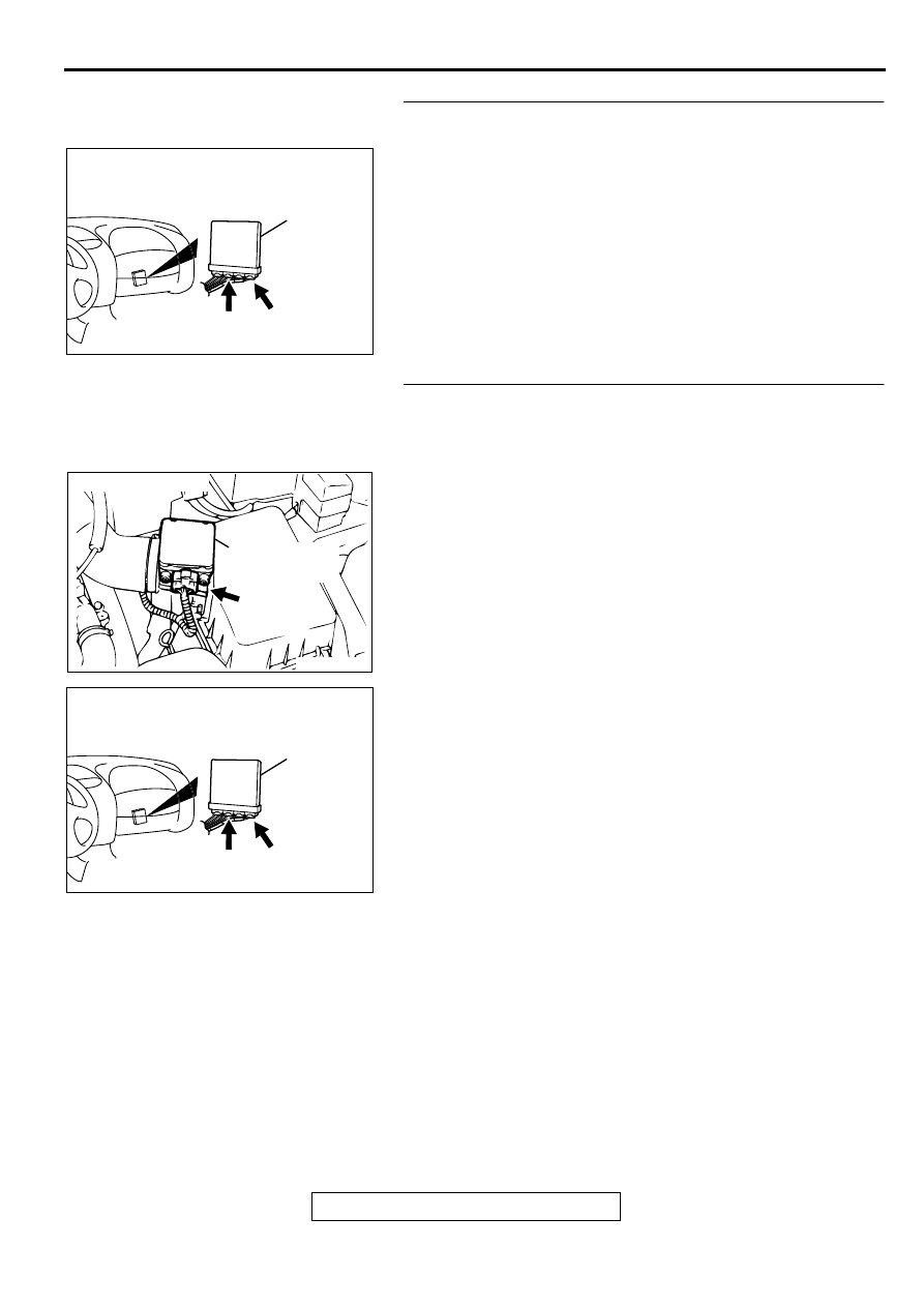
STEP 13. Check connector C-60 at ECM <M/T> or
connector C-54 at PCM <A/T> for damage.
Q: Is the connector in good condition?
YES : Go to Step 14.
NO : Repair or replace it. Refer to GROUP 00E, Harness
Connector Inspection (
). Then go to Step 19.
STEP 14. Check for open circuit and harness damage
between intake air temperature sensor connector B-14
terminal 5 and ECM connector C-60 terminal 92 <M/T> or
PCM connector C-54 terminal 57 <A/T>.
Q: Is the harness wire in good condition?
YES : Replace the ECM or PCM. Then go to Step 19.
NO : Repair it. Then go to Step 19.
AK000280
C-54
C-60
ECM<M/T>
OR
PCM<A/T>
CONNECTORS:C-60<M/T>,C-54<A/T>
BB
ACX02480
CONNECTOR : B-14
AG
INTAKE AIR
TEMPERATURE
SENSOR
AK000280
C-54
C-60
ECM<M/T>
OR
PCM<A/T>
CONNECTORS:C-60<M/T>,C-54<A/T>
BB
MULTIPORT FUEL INJECTION (MFI) DIAGNOSIS
TSB Revision
MULTIPORT FUEL INJECTION (MFI) <2.4L ENGINE>
13A-66
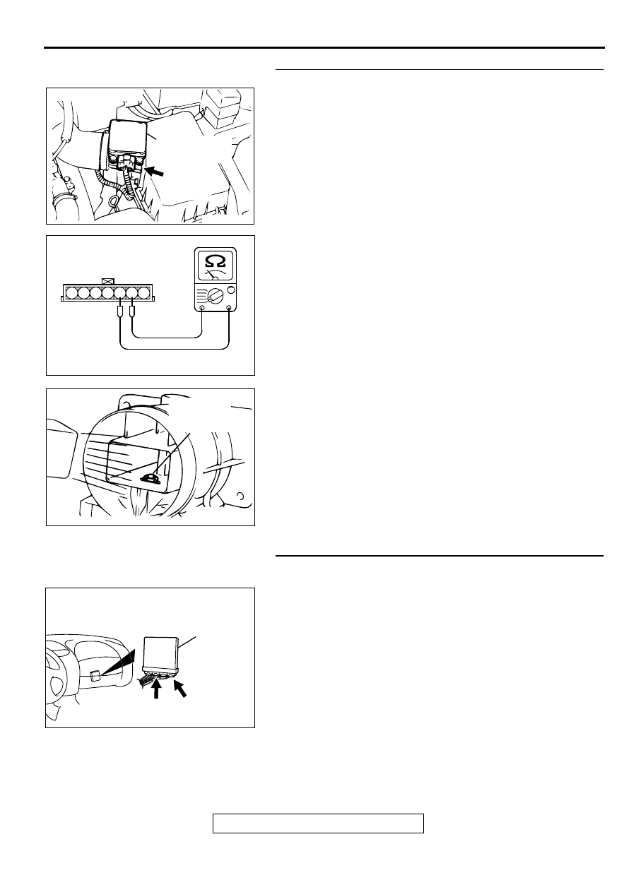
STEP 15. Check the intake air temperature sensor.
(1) Disconnect the intake air temperature sensor connector B-
14
(2) Measure the resistance between intake air temperature
sensor side connector terminal 5 and 6.
(3) Measure resistance while heating the sensor using a hair
drier.
Standard value:
5.3
−
6.7 k
Ω
[at 0
°
C (32
°
F)]
2.3
−
3.0 k
Ω
[at 20
°
C (68
°
F)]
1.0
−
1.5 k
Ω
[at 40
°
C (104
°
F)]
0.30
−
0.42 k
Ω
[at 80
°
C (176
°
F)]
Q: Is the resistance at the standard value?
YES : Go to Step 16.
NO : Replace the volume air flow sensor. Then go to Step
19.
STEP 16. Check connector C-60 at ECM <M/T> or
connector C-54 at PCM <A/T> for damage.
Q: Is the connector in good condition?
YES : Go to Step 17.
NO : Repair or replace it. Refer to GROUP 00E, Harness
Connector Inspection (
). Then go to Step 19.
ACX02480
CONNECTOR : B-14
AG
INTAKE AIR
TEMPERATURE
SENSOR
AK000319AB
1 2 3 4 5 6 7
INTAKE AIR TEMPERATURE
SENSOR SIDE CONNECTOR
AKX01621 AB
INTAKE AIR
TEMPERATURE
SENSOR
AK000280
C-54
C-60
ECM<M/T>
OR
PCM<A/T>
CONNECTORS:C-60<M/T>,C-54<A/T>
BB
Нет комментариевНе стесняйтесь поделиться с нами вашим ценным мнением.
Текст